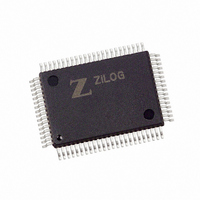
Z16F2810FI20EG Zilog, Z16F2810FI20EG Datasheet - Page 74

Z16F2810FI20EG
Manufacturer Part Number
Z16F2810FI20EG
Description
IC ZNEO MCU FLASH 128K 80QFP
Manufacturer
Zilog
Series
Encore!® ZNEOr
Datasheet
1.Z16F2800100ZCOG.pdf
(388 pages)
Specifications of Z16F2810FI20EG
Core Processor
ZNEO
Core Size
16-Bit
Speed
20MHz
Connectivity
I²C, IrDA, LIN, SPI, UART/USART
Peripherals
Brown-out Detect/Reset, DMA, POR, PWM, WDT
Number Of I /o
60
Program Memory Size
128KB (128K x 8)
Program Memory Type
FLASH
Ram Size
4K x 8
Voltage - Supply (vcc/vdd)
2.7 V ~ 3.6 V
Data Converters
A/D 12x10b
Oscillator Type
Internal
Operating Temperature
-40°C ~ 105°C
Package / Case
80-BQFP
Data Bus Width
16 bit
Data Ram Size
4 B
Interface Type
ESPI, I2C, UART
Maximum Clock Frequency
20 MHz
Number Of Programmable I/os
60
Number Of Timers
4
Operating Supply Voltage
2.7 V to 3.6 V
Maximum Operating Temperature
+ 105 C
Mounting Style
SMD/SMT
Minimum Operating Temperature
- 40 C
On-chip Adc
10 bit, 12 Channel
For Use With
770-1003 - ISP 4PORT FOR ZILOG ZNEO MCU269-4537 - DEV KIT FOR Z16F ZNEO
Lead Free Status / RoHS Status
Lead free / RoHS Compliant
Eeprom Size
-
Lead Free Status / Rohs Status
Details
Available stocks
Company
Part Number
Manufacturer
Quantity
Price
- Current page: 74 of 388
- Download datasheet (22Mb)
System Reset
PS022008-0810
During a System Reset, the ZNEO Z16F Series device is held in Reset for 66 cycles of the
IPO. At the beginning of Reset, all GPIO pins are configured as inputs. All GPIO
programmable pull-ups are disabled.
At the start of a System Reset, the motor control PWM outputs are forced to high-
impedance momentarily. When the option bits that control the off-state have been properly
evaluated, the PWM outputs are forced to the programmed off-state.
During Reset, the ZNEO CPU and on-chip peripherals are non-active; however, the IPO
and WDT oscillator continue to run. During the first 50 clock cycles, the internal option
bit registers are initialized, after which the system clock for the core and peripherals
begins operating. The ZNEO CPU and on-chip peripherals remain non-active through the
next 16 cycles of the system clock, after which the internal reset signal is deasserted.
On Reset, control registers within the register file that have a defined reset value are
loaded with their reset values. Other control registers (including the Flags) and general-
purpose RAM are undefined following Reset. The ZNEO CPU fetches the Reset vector at
program memory address
execution begins at the Reset vector address.
Table 19
text provides more detailed information on the individual Reset sources. Note that a
POR/VBO event always has priority over all other possible reset sources to ensure that a
full System Reset occurs.
Table 19. System Reset Sources and Resulting Reset Action
Operating Mode
NORMAL or HALT modes
STOP mode
lists the System Reset sources as a function of the operating mode. The following
0004H
P R E L I M I N A R Y
System Reset Source
POR/VBO
WDT time-out
when configured for Reset
RESET pin assertion
Write RSTSCR[0] to 1
Fault detect logic reset
POR/VBO
RESET pin assertion
Fault detect logic reset
and loads that value into the program counter. Program
Reset and Stop Mode Recovery
Product Specification
System Reset
System Reset
System Reset
Action
System Reset
System Reset
System Reset
System Reset
System Reset
ZNEO
Z16F Series
59
Related parts for Z16F2810FI20EG
Image
Part Number
Description
Manufacturer
Datasheet
Request
R

Part Number:
Description:
Communication Controllers, ZILOG INTELLIGENT PERIPHERAL CONTROLLER (ZIP)
Manufacturer:
Zilog, Inc.
Datasheet:

Part Number:
Description:
KIT DEV FOR Z8 ENCORE 16K TO 64K
Manufacturer:
Zilog
Datasheet:

Part Number:
Description:
KIT DEV Z8 ENCORE XP 28-PIN
Manufacturer:
Zilog
Datasheet:

Part Number:
Description:
DEV KIT FOR Z8 ENCORE 8K/4K
Manufacturer:
Zilog
Datasheet:

Part Number:
Description:
KIT DEV Z8 ENCORE XP 28-PIN
Manufacturer:
Zilog
Datasheet:

Part Number:
Description:
DEV KIT FOR Z8 ENCORE 4K TO 8K
Manufacturer:
Zilog
Datasheet:

Part Number:
Description:
CMOS Z8 microcontroller. ROM 16 Kbytes, RAM 256 bytes, speed 16 MHz, 32 lines I/O, 3.0V to 5.5V
Manufacturer:
Zilog, Inc.
Datasheet:

Part Number:
Description:
Low-cost microcontroller. 512 bytes ROM, 61 bytes RAM, 8 MHz
Manufacturer:
Zilog, Inc.
Datasheet:

Part Number:
Description:
Z8 4K OTP Microcontroller
Manufacturer:
Zilog, Inc.
Datasheet:

Part Number:
Description:
CMOS SUPER8 ROMLESS MCU
Manufacturer:
Zilog, Inc.
Datasheet:

Part Number:
Description:
SL1866 CMOSZ8 OTP Microcontroller
Manufacturer:
Zilog, Inc.
Datasheet:

Part Number:
Description:
SL1866 CMOSZ8 OTP Microcontroller
Manufacturer:
Zilog, Inc.
Datasheet:

Part Number:
Description:
OTP (KB) = 1, RAM = 125, Speed = 12, I/O = 14, 8-bit Timers = 2, Comm Interfaces Other Features = Por, LV Protect, Voltage = 4.5-5.5V
Manufacturer:
Zilog, Inc.
Datasheet:

Part Number:
Description:
Manufacturer:
Zilog, Inc.
Datasheet:


