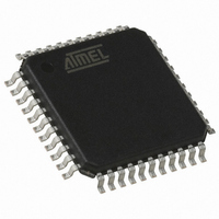
AT89C51CC03CA-RLTUM Atmel, AT89C51CC03CA-RLTUM Datasheet - Page 29

AT89C51CC03CA-RLTUM
Manufacturer Part Number
AT89C51CC03CA-RLTUM
Description
IC 8051 MCU 64K FLASH 44-VQFP
Manufacturer
Atmel
Series
AT89C CANr
Datasheet
1.AT89C51CC03C-S3RIM.pdf
(198 pages)
Specifications of AT89C51CC03CA-RLTUM
Core Processor
8051
Core Size
8-Bit
Speed
40MHz
Connectivity
CAN, UART/USART
Peripherals
POR, PWM, WDT
Number Of I /o
36
Program Memory Size
64KB (64K x 8)
Program Memory Type
FLASH
Eeprom Size
2K x 8
Ram Size
2.25K x 8
Voltage - Supply (vcc/vdd)
3 V ~ 5.5 V
Data Converters
A/D 8x10b
Oscillator Type
External
Operating Temperature
-40°C ~ 85°C
Package / Case
44-TQFP, 44-VQFP
Processor Series
AT89x
Core
8051
Data Bus Width
8 bit
Data Ram Size
2304 B
Interface Type
UART, SPI
Maximum Clock Frequency
60 MHz
Number Of Programmable I/os
36
Number Of Timers
2
Operating Supply Voltage
3 V to 5.5 V
Maximum Operating Temperature
+ 85 C
Mounting Style
SMD/SMT
3rd Party Development Tools
PK51, CA51, A51, ULINK2
Minimum Operating Temperature
- 40 C
On-chip Adc
10 bit, 8 Channel
Package
44VQFP
Device Core
8051
Family Name
AT89
Maximum Speed
60 MHz
For Use With
AT89OCD-01 - USB EMULATOR FOR AT8XC51 MCU
Lead Free Status / RoHS Status
Lead free / RoHS Compliant
Available stocks
Company
Part Number
Manufacturer
Quantity
Price
Company:
Part Number:
AT89C51CC03CA-RLTUM
Manufacturer:
ADI
Quantity:
141
Power Monitor
Description
Figure 14. Power Monitor Block Diagram
4182O–CAN–09/08
The POR/PFD function monitors the internal power-supply of the CPU core memories
and the peripherals, and if needed, suspends their activity when the internal power sup-
ply falls below a safety threshold. This is achieved by applying an internal reset to them.
By generating the Reset the Power Monitor insures a correct start up when
AT89C51CC03 is powered up.
In order to startup and maintain the microcontroller in correct operating mode, V
to be stabilized in the V
nominal amplitude compatible with logic level VIH/VIL.
These parameters are controlled during the three phases: power-up, normal operation
and power going down. See Figure 14.
Note:
The Voltage regulator generates a regulated internal supply for the CPU core the mem-
ories and the peripherals. Spikes on the external Vcc are smoothed by the voltage
regulator.
The Power fail detect monitor the supply generated by the voltage regulator and gener-
ate a reset if this supply falls below a safety threshold as illustrated in the Figure 15.
RST pin
XTAL1
1. Once XTAL1 high and low levels reach above and below VIH/VIL a 1024 clock period
delay will extend the reset coming from the Power Fail Detect. If the power falls below
the Power Fail Detect thresthold level, the reset will be applied immediately.
PCA
Watchdog
Voltage Regulator
Power Fail Detect
Power On Reset
(1)
Hardware
Watchdog
VCC
CC
operating range and the oscillator has to be stabilized with a
Regulated
Supply
Internal Reset
Peripherals
CPU core
Memories
AT89C51CC03
CC
has
29


