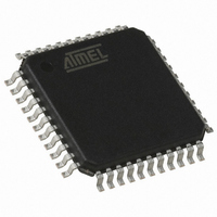
AT89C51CC03CA-RLTUM Atmel, AT89C51CC03CA-RLTUM Datasheet - Page 117

AT89C51CC03CA-RLTUM
Manufacturer Part Number
AT89C51CC03CA-RLTUM
Description
IC 8051 MCU 64K FLASH 44-VQFP
Manufacturer
Atmel
Series
AT89C CANr
Datasheet
1.AT89C51CC03C-S3RIM.pdf
(198 pages)
Specifications of AT89C51CC03CA-RLTUM
Core Processor
8051
Core Size
8-Bit
Speed
40MHz
Connectivity
CAN, UART/USART
Peripherals
POR, PWM, WDT
Number Of I /o
36
Program Memory Size
64KB (64K x 8)
Program Memory Type
FLASH
Eeprom Size
2K x 8
Ram Size
2.25K x 8
Voltage - Supply (vcc/vdd)
3 V ~ 5.5 V
Data Converters
A/D 8x10b
Oscillator Type
External
Operating Temperature
-40°C ~ 85°C
Package / Case
44-TQFP, 44-VQFP
Processor Series
AT89x
Core
8051
Data Bus Width
8 bit
Data Ram Size
2304 B
Interface Type
UART, SPI
Maximum Clock Frequency
60 MHz
Number Of Programmable I/os
36
Number Of Timers
2
Operating Supply Voltage
3 V to 5.5 V
Maximum Operating Temperature
+ 85 C
Mounting Style
SMD/SMT
3rd Party Development Tools
PK51, CA51, A51, ULINK2
Minimum Operating Temperature
- 40 C
On-chip Adc
10 bit, 8 Channel
Package
44VQFP
Device Core
8051
Family Name
AT89
Maximum Speed
60 MHz
For Use With
AT89OCD-01 - USB EMULATOR FOR AT8XC51 MCU
Lead Free Status / RoHS Status
Lead free / RoHS Compliant
Available stocks
Company
Part Number
Manufacturer
Quantity
Price
Company:
Part Number:
AT89C51CC03CA-RLTUM
Manufacturer:
ADI
Quantity:
141
4182O–CAN–09/08
Table 63. CANPAGE Register
CANPAGE (S:B1h)
CAN Message Object Page Register
Reset Value = 0000 0000b
Table 64. CANCONCH Register
CANCONCH (S:B3h)
CAN Message Object Control and DLC Register
No default value after reset
CONCH 1
Number
Number
CHNB 3
Bit
Bit
7-4
2-0
7-6
3-0
7
7
3
5
4
Bit Mnemonic Description
Bit Mnemonic Description
CONCH 0
CHNB 2
CONCH1:0
CHNB3:0
INDX2:0
DLC3:0
RPLV
AINC
6
6
IDE
CHNB 1
Selection of Message Object Number
The available numbers are: 0 to 14 (see Figure 48).
Auto Increment of the Index (active low)
0 - auto-increment of the index (default value).
1 - non-auto-increment of the index.
Index
Byte location of the data field for the defined message object (see Figure 48).
Configuration of Message Object
CONCH1 CONCH0
Note: The user must re-write the configuration to enable the corresponding bit
in the CANEN1:2 registers.
Reply Valid
Used in the automatic reply mode after receiving a remote frame
0 - reply not ready.
1 - reply ready and valid.
Identifier Extension
0 - CAN standard rev 2.0 A (ident = 11 bits).
1 - CAN standard rev 2.0 B (ident = 29 bits).
Data Length Code
Number of Bytes in the data field of the message.
The range of DLC is from 0 up to 8.
This value is updated when a frame is received (data or remote frame).
If the expected DLC differs from the incoming DLC, a warning appears in the
CANSTCH register.
RPLV
5
5
0
0
1
1
0: disable
1: Launch transmission
0: Enable Reception
1: Enable Reception Buffer
CHNB 0
IDE
4
4
DLC 3
AINC
3
3
INDX2
DLC 2
AT89C51CC03
2
2
INDX1
DLC 1
1
1
INDX0
DLC 0
0
0
117


