ATTINY48-MMU Atmel, ATTINY48-MMU Datasheet - Page 83
ATTINY48-MMU
Manufacturer Part Number
ATTINY48-MMU
Description
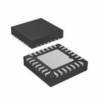
MCU AVR 5K FLASH 12MHZ 28-QFN
Manufacturer
Atmel
Series
AVR® ATtinyr
Specifications of ATTINY48-MMU
Core Processor
AVR
Core Size
8-Bit
Speed
12MHz
Connectivity
I²C, SPI
Peripherals
Brown-out Detect/Reset, POR, WDT
Number Of I /o
24
Program Memory Size
4KB (2K x 16)
Program Memory Type
FLASH
Eeprom Size
64 x 8
Ram Size
256 x 8
Voltage - Supply (vcc/vdd)
1.8 V ~ 5.5 V
Data Converters
A/D 6x10b
Oscillator Type
Internal
Operating Temperature
-40°C ~ 85°C
Package / Case
28-VQFN Exposed Pad, 28-HVQFN, 28-SQFN, 28-DHVQFN
Processor Series
ATTINY4x
Core
AVR8
Data Bus Width
8 bit
Data Ram Size
256 B
Interface Type
2-Wire, I2S, SPI
Maximum Clock Frequency
12 MHz
Number Of Programmable I/os
24
Number Of Timers
2
Maximum Operating Temperature
+ 85 C
Mounting Style
SMD/SMT
3rd Party Development Tools
EWAVR, EWAVR-BL
Development Tools By Supplier
ATAVRDRAGON, ATSTK500, ATSTK600, ATAVRISP2, ATAVRONEKIT
Minimum Operating Temperature
- 40 C
On-chip Adc
10 bit, 6 Channel
Package
28VQFN EP
Device Core
AVR
Family Name
ATtiny
Maximum Speed
12 MHz
Operating Supply Voltage
2.5|3.3|5 V
For Use With
ATAVRDRAGON - KIT DRAGON 32KB FLASH MEM AVR
Lead Free Status / RoHS Status
Lead free / RoHS Compliant


11.5.2
11.6
11.6.1
11.6.2
8008G–AVR–04/11
Modes of Operation
Using the Output Compare Unit
Normal Mode
Clear Timer on Compare Match (CTC) Mode
ized to the same value as TCNT0 without triggering an interrupt when the Timer/Counter clock is
enabled.
Since writing TCNT0 in any mode of operation will block all compare matches for one timer clock
cycle, there are risks involved when changing TCNT0 when using the Output Compare Unit,
independently of whether the Timer/Counter is running or not. If the value written to TCNT0
equals the OCR0x value, the compare match will be missed, resulting in incorrect waveform
generation.
The mode of operation, i.e., the behavior of the Timer/Counter and the Output Compare pins, is
defined by the CTC0 bit.
For detailed timing information refer to
The simplest mode of operation is the Normal mode (CTC0 = 0). In this mode the counting direc-
tion is always up (incrementing), and no counter clear is performed. The counter simply overruns
when it passes its maximum 8-bit value (TOP = 0xFF) and then restarts from the bottom (0x00).
In normal operation the Timer/Counter Overflow Flag (TOV0) will be set in the same timer clock
cycle as the TCNT0 becomes zero. The TOV0 Flag in this case behaves like a ninth bit, except
that it is only set, not cleared. However, combined with the timer overflow interrupt that automat-
ically clears the TOV0 Flag, the timer resolution can be increased by software. There are no
special cases to consider in the Normal mode, a new counter value can be written anytime.
The Output Compare unit can be used to generate interrupts at some given time.
In Clear Timer on Compare or CTC mode (CTC0 = 1), the OCR0A Register is used to manipu-
late the counter resolution. In CTC mode the counter is cleared to zero when the counter value
(TCNT0) matches the OCR0A. The OCR0A defines the top value for the counter, hence also its
resolution. This mode allows greater control of the compare match output frequency. It also sim-
plifies the operation of counting external events.
The timing diagram for the CTC mode is shown in
increases until a compare match occurs between TCNT0 and OCR0A, and then counter
(TCNT0) is cleared.
Figure 11-4. CTC Mode, Timing Diagram
TCNTn
Period
1
2
“Timer/Counter Timing Diagrams” on page
3
Figure
4
11-4. The counter value (TCNT0)
ATtiny48/88
OCnx Interrupt Flag Set
84.
83
Related parts for ATTINY48-MMU
Image
Part Number
Description
Manufacturer
Datasheet
Request
R

Part Number:
Description:
Manufacturer:
Atmel Corporation
Datasheet:

Part Number:
Description:
MCU AVR 4K ISP FLASH 1.8V 32TQFP
Manufacturer:
Atmel
Datasheet:

Part Number:
Description:
MCU AVR 4K ISP FLASH 1.8V 32-QFN
Manufacturer:
Atmel
Datasheet:

Part Number:
Description:
MCU AVR 4K ISP FLASH 1.8V 28-DIP
Manufacturer:
Atmel
Datasheet:

Part Number:
Description:
MCU AVR 4KB FLASH 12MHZ 32TQFP
Manufacturer:
Atmel
Datasheet:
Part Number:
Description:
MCU AVR 4KB FLASH 12MHZ 32QFN
Manufacturer:
Atmel
Datasheet:

Part Number:
Description:
MCU AVR 4KB FLASH 12MHZ 28-VQFN
Manufacturer:
Atmel
Datasheet:
Part Number:
Description:
MCU AVR 4KB FLASH 12MHZ 28QFN
Manufacturer:
Atmel
Datasheet:
Part Number:
Description:
8-bit Microcontrollers - MCU 4KB FL,64B EE, 256B SRAM-12MHz
Manufacturer:
Atmel
Part Number:
Description:
8-bit Microcontrollers - MCU Microcontroller
Manufacturer:
Atmel
Part Number:
Description:
Manufacturer:
Atmel Corporation
Datasheet: