ATTINY48-MMU Atmel, ATTINY48-MMU Datasheet - Page 184
ATTINY48-MMU
Manufacturer Part Number
ATTINY48-MMU
Description
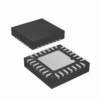
MCU AVR 5K FLASH 12MHZ 28-QFN
Manufacturer
Atmel
Series
AVR® ATtinyr
Specifications of ATTINY48-MMU
Core Processor
AVR
Core Size
8-Bit
Speed
12MHz
Connectivity
I²C, SPI
Peripherals
Brown-out Detect/Reset, POR, WDT
Number Of I /o
24
Program Memory Size
4KB (2K x 16)
Program Memory Type
FLASH
Eeprom Size
64 x 8
Ram Size
256 x 8
Voltage - Supply (vcc/vdd)
1.8 V ~ 5.5 V
Data Converters
A/D 6x10b
Oscillator Type
Internal
Operating Temperature
-40°C ~ 85°C
Package / Case
28-VQFN Exposed Pad, 28-HVQFN, 28-SQFN, 28-DHVQFN
Processor Series
ATTINY4x
Core
AVR8
Data Bus Width
8 bit
Data Ram Size
256 B
Interface Type
2-Wire, I2S, SPI
Maximum Clock Frequency
12 MHz
Number Of Programmable I/os
24
Number Of Timers
2
Maximum Operating Temperature
+ 85 C
Mounting Style
SMD/SMT
3rd Party Development Tools
EWAVR, EWAVR-BL
Development Tools By Supplier
ATAVRDRAGON, ATSTK500, ATSTK600, ATAVRISP2, ATAVRONEKIT
Minimum Operating Temperature
- 40 C
On-chip Adc
10 bit, 6 Channel
Package
28VQFN EP
Device Core
AVR
Family Name
ATtiny
Maximum Speed
12 MHz
Operating Supply Voltage
2.5|3.3|5 V
For Use With
ATAVRDRAGON - KIT DRAGON 32KB FLASH MEM AVR
Lead Free Status / RoHS Status
Lead free / RoHS Compliant


19.0.3
19.1
184
Addressing the Flash During Self-Programming
ATtiny48/88
Performing a Page Write
To execute Page Write, set up the address in the Z-pointer, write “00000101” to SPMCSR and
execute SPM within four clock cycles after writing SPMCSR. The data in R1 and R0 is ignored.
The page address must be written to PCPAGE. Other bits in the Z-pointer must be written to
zero during this operation.
The CPU is halted during the Page Write operation.
The Z-pointer is used to address the SPM commands.
Since the Flash is organized in pages (see
Counter can be treated as having two different sections. One section, consisting of the least sig-
nificant bits, is addressing the words within a page, while the most significant bits are addressing
the pages. This is shown in
are addressed independently. Therefore it is of major importance that the software addresses
the same page in both the Page Erase and Page Write operation.
The LPM instruction uses the Z-pointer to store the address. Since this instruction addresses the
Flash byte-by-byte, also the LSB (bit Z0) of the Z-pointer is used.
Figure 19-1. Addressing the Flash During SPM
Note:
Bit
ZH (R31)
ZL (R30)
Z - REGISTER
1. The different variables used in
PROGRAM MEMORY
BIT
PAGE
PROGRAM
COUNTER
15
Z15
15
Z7
7
PAGE ADDRESS
WITHIN THE FLASH
ZPCMSB
PCMSB
Z14
Z6
14
6
Figure
PCPAGE
Z13
13
Z5
19-1. Note that the Page Erase and Page Write operations
5
Figure 19-1
ZPAGEMSB
PAGEMSB
PCWORD
Z12
“Memory Parametrics” on page
Z4
12
4
WORD ADDRESS
WITHIN A PAGE
(1)
are listed in
1
Z11
0
0
11
Z3
3
INSTRUCTION WORD
PAGE
Table 21-1 on page
Z10
10
Z2
2
Z9
Z1
9
1
PCWORD[PAGEMSB:0]:
00
01
02
PAGEEND
191), the Program
191.
Z8
Z0
8
0
8008G–AVR–04/11
Related parts for ATTINY48-MMU
Image
Part Number
Description
Manufacturer
Datasheet
Request
R

Part Number:
Description:
Manufacturer:
Atmel Corporation
Datasheet:

Part Number:
Description:
MCU AVR 4K ISP FLASH 1.8V 32TQFP
Manufacturer:
Atmel
Datasheet:

Part Number:
Description:
MCU AVR 4K ISP FLASH 1.8V 32-QFN
Manufacturer:
Atmel
Datasheet:

Part Number:
Description:
MCU AVR 4K ISP FLASH 1.8V 28-DIP
Manufacturer:
Atmel
Datasheet:

Part Number:
Description:
MCU AVR 4KB FLASH 12MHZ 32TQFP
Manufacturer:
Atmel
Datasheet:
Part Number:
Description:
MCU AVR 4KB FLASH 12MHZ 32QFN
Manufacturer:
Atmel
Datasheet:

Part Number:
Description:
MCU AVR 4KB FLASH 12MHZ 28-VQFN
Manufacturer:
Atmel
Datasheet:
Part Number:
Description:
MCU AVR 4KB FLASH 12MHZ 28QFN
Manufacturer:
Atmel
Datasheet:
Part Number:
Description:
8-bit Microcontrollers - MCU 4KB FL,64B EE, 256B SRAM-12MHz
Manufacturer:
Atmel
Part Number:
Description:
8-bit Microcontrollers - MCU Microcontroller
Manufacturer:
Atmel
Part Number:
Description:
Manufacturer:
Atmel Corporation
Datasheet: