ATTINY48-MMU Atmel, ATTINY48-MMU Datasheet - Page 158
ATTINY48-MMU
Manufacturer Part Number
ATTINY48-MMU
Description
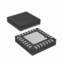
MCU AVR 5K FLASH 12MHZ 28-QFN
Manufacturer
Atmel
Series
AVR® ATtinyr
Specifications of ATTINY48-MMU
Core Processor
AVR
Core Size
8-Bit
Speed
12MHz
Connectivity
I²C, SPI
Peripherals
Brown-out Detect/Reset, POR, WDT
Number Of I /o
24
Program Memory Size
4KB (2K x 16)
Program Memory Type
FLASH
Eeprom Size
64 x 8
Ram Size
256 x 8
Voltage - Supply (vcc/vdd)
1.8 V ~ 5.5 V
Data Converters
A/D 6x10b
Oscillator Type
Internal
Operating Temperature
-40°C ~ 85°C
Package / Case
28-VQFN Exposed Pad, 28-HVQFN, 28-SQFN, 28-DHVQFN
Processor Series
ATTINY4x
Core
AVR8
Data Bus Width
8 bit
Data Ram Size
256 B
Interface Type
2-Wire, I2S, SPI
Maximum Clock Frequency
12 MHz
Number Of Programmable I/os
24
Number Of Timers
2
Maximum Operating Temperature
+ 85 C
Mounting Style
SMD/SMT
3rd Party Development Tools
EWAVR, EWAVR-BL
Development Tools By Supplier
ATAVRDRAGON, ATSTK500, ATSTK600, ATAVRISP2, ATAVRONEKIT
Minimum Operating Temperature
- 40 C
On-chip Adc
10 bit, 6 Channel
Package
28VQFN EP
Device Core
AVR
Family Name
ATtiny
Maximum Speed
12 MHz
Operating Supply Voltage
2.5|3.3|5 V
For Use With
ATAVRDRAGON - KIT DRAGON 32KB FLASH MEM AVR
Lead Free Status / RoHS Status
Lead free / RoHS Compliant


15.11.3
158
ATtiny48/88
TWSR – TWI Status Register
• Bit 5 – TWSTA: TWI START Condition Bit
The application writes the TWSTA bit to one when it desires to become a Master on the 2-wire
Serial Bus. The TWI hardware checks if the bus is available, and generates a START condition
on the bus if it is free. However, if the bus is not free, the TWI waits until a STOP condition is
detected, and then generates a new START condition to claim the bus Master status. TWSTA
must be cleared by software when the START condition has been transmitted.
• Bit 4 – TWSTO: TWI STOP Condition Bit
Writing the TWSTO bit to one in Master mode will generate a STOP condition on the 2-wire
Serial Bus. When the STOP condition is executed on the bus, the TWSTO bit is cleared auto-
matically. In Slave mode, setting the TWSTO bit can be used to recover from an error condition.
This will not generate a STOP condition, but the TWI returns to a well-defined unaddressed
Slave mode and releases the SCL and SDA lines to a high impedance state.
• Bit 3 – TWWC: TWI Write Collision Flag
The TWWC bit is set when attempting to write to the TWI Data Register – TWDR when TWINT is
low. This flag is cleared by writing the TWDR Register when TWINT is high.
• Bit 2 – TWEN: TWI Enable Bit
The TWEN bit enables TWI operation and activates the TWI interface. When TWEN is written to
one, the TWI takes control over the I/O pins connected to the SCL and SDA pins, enabling the
slew-rate limiters and spike filters. If this bit is written to zero, the TWI is switched off and all TWI
transmissions are terminated, regardless of any ongoing operation.
• Bit 1 – Res: Reserved Bit
This bit is reserved and will always read as zero.
• Bit 0 – TWIE: TWI Interrupt Enable
When this bit is written to one, and the I-bit in SREG is set, the TWI interrupt request will be acti-
vated for as long as the TWINT Flag is high.
• Bits 7:3 – TWS: TWI Status
These 5 bits reflect the status of the TWI logic and the 2-wire Serial Bus. The different status
codes are described later in this section. Note that the value read from TWSR contains both the
5-bit status value and the 2-bit prescaler value. The application designer should mask the pres-
caler bits to zero when checking the Status bits. This makes status checking independent of
prescaler setting. This approach is used in this datasheet, unless otherwise noted.
• Bit 2 – Res: Reserved Bit
This bit is reserved and will always read as zero.
Bit
(0xB9)
Read/Write
Initial Value
TWS7
R
7
1
TWS6
R
6
1
TWS5
R
5
1
TWS4
R
4
1
TWS3
R
3
1
R
2
–
0
TWPS1
R/W
1
0
TWPS0
R/W
0
0
8008G–AVR–04/11
TWSR
Related parts for ATTINY48-MMU
Image
Part Number
Description
Manufacturer
Datasheet
Request
R

Part Number:
Description:
Manufacturer:
Atmel Corporation
Datasheet:

Part Number:
Description:
MCU AVR 4K ISP FLASH 1.8V 32TQFP
Manufacturer:
Atmel
Datasheet:

Part Number:
Description:
MCU AVR 4K ISP FLASH 1.8V 32-QFN
Manufacturer:
Atmel
Datasheet:

Part Number:
Description:
MCU AVR 4K ISP FLASH 1.8V 28-DIP
Manufacturer:
Atmel
Datasheet:

Part Number:
Description:
MCU AVR 4KB FLASH 12MHZ 32TQFP
Manufacturer:
Atmel
Datasheet:
Part Number:
Description:
MCU AVR 4KB FLASH 12MHZ 32QFN
Manufacturer:
Atmel
Datasheet:

Part Number:
Description:
MCU AVR 4KB FLASH 12MHZ 28-VQFN
Manufacturer:
Atmel
Datasheet:
Part Number:
Description:
MCU AVR 4KB FLASH 12MHZ 28QFN
Manufacturer:
Atmel
Datasheet:
Part Number:
Description:
8-bit Microcontrollers - MCU 4KB FL,64B EE, 256B SRAM-12MHz
Manufacturer:
Atmel
Part Number:
Description:
8-bit Microcontrollers - MCU Microcontroller
Manufacturer:
Atmel
Part Number:
Description:
Manufacturer:
Atmel Corporation
Datasheet: