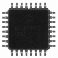
MC56F8013VFAE Freescale Semiconductor, MC56F8013VFAE Datasheet - Page 123

MC56F8013VFAE
Manufacturer Part Number
MC56F8013VFAE
Description
IC DIGITAL SIGNAL CTLR 32-LQFP
Manufacturer
Freescale Semiconductor
Series
56F8xxxr
Datasheet
1.MC56F8013VFAE.pdf
(126 pages)
Specifications of MC56F8013VFAE
Core Processor
56800
Core Size
16-Bit
Speed
32MHz
Connectivity
I²C, SCI, SPI
Peripherals
POR, PWM, WDT
Number Of I /o
26
Program Memory Size
16KB (8K x 16)
Program Memory Type
FLASH
Ram Size
2K x 16
Voltage - Supply (vcc/vdd)
3 V ~ 3.6 V
Data Converters
A/D 6x12b
Oscillator Type
Internal
Operating Temperature
-40°C ~ 105°C
Package / Case
32-LQFP
Product
DSCs
Data Bus Width
16 bit
Processor Series
MC56F80xx
Core
56800E
Numeric And Arithmetic Format
Fixed-Point
Device Million Instructions Per Second
32 MIPs
Maximum Clock Frequency
32 MHz
Number Of Programmable I/os
26
Data Ram Size
4 KB
Operating Supply Voltage
3.3 V
Maximum Operating Temperature
+ 105 C
Mounting Style
SMD/SMT
Data Rom Size
16 KB
Development Tools By Supplier
MC56F8037EVM, DEMO56F8014-EE, DEMO56F8013-EE
Interface Type
SCI, SPI, I2C
Minimum Operating Temperature
- 40 C
For Use With
CPA56F8013 - BOARD SOCKET FOR MC56F8013APMOTOR56F8000E - KIT DEMO MOTOR CTRL SYSTEMDEMO56F8013-EE - BOARD DEMO FOR 56F8013
Lead Free Status / RoHS Status
Lead free / RoHS Compliant
Eeprom Size
-
Lead Free Status / Rohs Status
Lead free / RoHS Compliant
Available stocks
Company
Part Number
Manufacturer
Quantity
Price
Company:
Part Number:
MC56F8013VFAE
Manufacturer:
FREESCAL
Quantity:
210
Company:
Part Number:
MC56F8013VFAE
Manufacturer:
Freescale Semiconductor
Quantity:
10 000
Part Number:
MC56F8013VFAE
Manufacturer:
FREESCALE
Quantity:
20 000
Company:
Part Number:
MC56F8013VFAEN
Manufacturer:
Freescale
Quantity:
52
Part Number:
MC56F8013VFAEN
Manufacturer:
FREESCALE
Quantity:
20 000
Company:
Part Number:
MC56F8013VFAER2
Manufacturer:
Freescale Semiconductor
Quantity:
10 000
Freescale Semiconductor
•
•
•
•
•
•
•
Bypass the V
PCB trace lengths should be minimal for high-frequency signals
Consider all device loads as well as parasitic capacitance due to PCB traces when calculating capacitance.
This is especially critical in systems with higher capacitive loads that could create higher transient currents
in the V
Take special care to minimize noise levels on the V
Using separate power planes for V
recommended. Connect the separate analog and digital power and ground planes as close as possible to
power supply outputs. If both analog circuit and digital circuit are powered by the same power supply, it is
advisable to connect a small inductor or ferrite bead in serial with both V
It is highly desirable to physically separate analog components from noisy digital components by ground
planes. Do not place an analog trace in parallel with digital traces. It is also desirable to place an analog
ground trace around an analog signal trace to isolate it from digital traces.
Because the Flash memory is programmed through the JTAG/EOnCE port, SPI, SCI or I
should provide an interface to this port if in-circuit Flash programming is desired.
DD
and V
DD
and V
SS
circuits.
SS
with approximately 100μF, plus the number of 0.1μF ceramic capacitors
56F8013/56F8011 Data Sheet, Rev. 12
DD
and V
DDA
and separate ground planes for V
REF
, V
DDA
and V
SSA
DDA
pins
and V
Electrical Design Considerations
SS
SSA
and V
traces.
2
C, the designer
SSA
is
123


