MC56F8002VWL Freescale Semiconductor, MC56F8002VWL Datasheet - Page 54
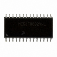
MC56F8002VWL
Manufacturer Part Number
MC56F8002VWL
Description
DSC 12K FLASH 32MHZ 28-SOIC
Manufacturer
Freescale Semiconductor
Series
56F8xxxr
Datasheet
1.MC56F8006DEMO.pdf
(100 pages)
Specifications of MC56F8002VWL
Core Processor
56800
Core Size
16-Bit
Speed
32MHz
Connectivity
I²C, LIN, SCI, SPI
Peripherals
LVD, POR, PWM, WDT
Number Of I /o
23
Program Memory Size
12KB (6K x 16)
Program Memory Type
FLASH
Ram Size
1K x 16
Voltage - Supply (vcc/vdd)
1.8 V ~ 3.6 V
Data Converters
A/D 15x12b
Oscillator Type
Internal
Operating Temperature
-40°C ~ 105°C
Package / Case
28-SOIC
Product
DSCs
Data Bus Width
16 bit
Processor Series
MC56F80xx
Core
56800E
Instruction Set Architecture
Dual Harvard
Device Million Instructions Per Second
32 MIPs
Maximum Clock Frequency
32 MHz
Number Of Programmable I/os
40
Data Ram Size
2 KB
Operating Supply Voltage
1.8 V to 3.6 V
Maximum Operating Temperature
+ 105 C
Mounting Style
SMD/SMT
Development Tools By Supplier
MC56F8006DEMO, APMOTOR56F8000E
Interface Type
LIN, I2C, SCI, SPI
Minimum Operating Temperature
- 40 C
For Use With
APMOTOR56F8000E - KIT DEMO MOTOR CTRL SYSTEM
Lead Free Status / RoHS Status
Lead free / RoHS Compliant
Eeprom Size
-
Lead Free Status / Rohs Status
Lead free / RoHS Compliant
Available stocks
Company
Part Number
Manufacturer
Quantity
Price

Part Number:
MC56F8002VWL
Manufacturer:
FREESCALE
Quantity:
20 000


Specifications
8.13
Tests are conducted using the input levels specified in
from the 50% to the 50% point, and rise and fall times are measured between the 10% and 90% points, as shown in
Figure 24
54
•
1
2
3
4
Oscillator crystal or resonator (PRECS = 1, CLK_MOD = 0)
Load capacitors
Feedback resistor
Series resistor
Crystal start-up time
Square wave input clock frequency (PRECS = 1, CLK_MOD = 1)
Data in Typical column was characterized at 3.0 V, 25 C or is typical recommended value.
Load capacitors (C
RANGE=HGO=0.
See crystal or resonator manufacturer’s recommendation.
Proper PC board layout procedures must be followed to achieve specifications.
Active state, when a bus or signal is driven, and enters a low impedance state
Input Signal
Low range (RANGE = 0)
High range (RANGE = 1), high gain (COHL =0)
High range (RANGE = 1), low power (COHL =1)
Low range (RANGE=0), low power (COHL =1)
Other oscillator settings
Low range, low power (RANGE=0, COHL =1)
Low range, high gain (RANGE=0, COHL =0)
High range (RANGE=1, COHL=X)
Low range, low power (RANGE = 0, COHL =1)
Low range, high gain (RANGE = 0, COHL =0)
High range, low power (RANGE = 1, COHL =1)
High range, high gain (RANGE = 1,COHL =0)
Low range, low power
Low range, high gain
High range, low power
High range, high gain
shows the definitions of the following signal states:
AC Electrical Characteristics
4 MHz
1 MHz
8 MHz
4
1
,C
Fall Time
2
), feedback resistor (R
Characteristic
Midpoint1
MC56F8006/MC56F8002 Digital Signal Controller, Rev. 3
Figure 23. Input Signal Measurement References
Table 27. Crystal Oscillator Characteristics
V
IH
The midpoint is V
F
Table
2
) and series resistor (R
2
Low
V
IL
21. Unless otherwise specified, propagation delays are measured
IL
+ (V
IH
– V
Symbol
IL
C
t
t
)/2.
CSTH
CSTL
f
R
1,
R
S
f
f
f
xtal
lo
hi
hi
S
) are incorporated internally when
C
F
Rise Time
2
High
Min
32
—
—
—
—
—
—
—
—
—
—
—
—
—
—
1
1
Typ
TBD
TBD
TBD
TBD
100
10
—
—
—
See Note
See Note
—
—
1
0
0
0
0
0
1
Freescale Semiconductor
90%
50%
10%
Max
38.4
50.0
16
10
20
—
—
—
—
—
—
—
—
—
—
2
3
8
0
Unit
MHz
MHz
MHz
MHz
M
ms
k
Figure
23.
Related parts for MC56F8002VWL
Image
Part Number
Description
Manufacturer
Datasheet
Request
R

Part Number:
Description:
Manufacturer:
Freescale Semiconductor, Inc
Datasheet:
Part Number:
Description:
Manufacturer:
Freescale Semiconductor, Inc
Datasheet:
Part Number:
Description:
Manufacturer:
Freescale Semiconductor, Inc
Datasheet:
Part Number:
Description:
Manufacturer:
Freescale Semiconductor, Inc
Datasheet:
Part Number:
Description:
Manufacturer:
Freescale Semiconductor, Inc
Datasheet:
Part Number:
Description:
Manufacturer:
Freescale Semiconductor, Inc
Datasheet:
Part Number:
Description:
Manufacturer:
Freescale Semiconductor, Inc
Datasheet:
Part Number:
Description:
Manufacturer:
Freescale Semiconductor, Inc
Datasheet:
Part Number:
Description:
Manufacturer:
Freescale Semiconductor, Inc
Datasheet:
Part Number:
Description:
Manufacturer:
Freescale Semiconductor, Inc
Datasheet:
Part Number:
Description:
Manufacturer:
Freescale Semiconductor, Inc
Datasheet:
Part Number:
Description:
Manufacturer:
Freescale Semiconductor, Inc
Datasheet:
Part Number:
Description:
Manufacturer:
Freescale Semiconductor, Inc
Datasheet:
Part Number:
Description:
Manufacturer:
Freescale Semiconductor, Inc
Datasheet:
Part Number:
Description:
Manufacturer:
Freescale Semiconductor, Inc
Datasheet: