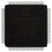
PIC24FJ128GA010-I/PT Microchip Technology, PIC24FJ128GA010-I/PT Datasheet - Page 188

PIC24FJ128GA010-I/PT
Manufacturer Part Number
PIC24FJ128GA010-I/PT
Description
IC PIC MCU FLASH 128K 100TQFP
Manufacturer
Microchip Technology
Series
PIC® 24Fr
Datasheets
1.PIC24FJ16GA002-ISS.pdf
(52 pages)
2.PIC24FJ64GA006-IPT.pdf
(240 pages)
3.PIC24FJ64GA006-IPT.pdf
(22 pages)
4.PIC24FJ128GA008-IPT.pdf
(12 pages)
5.PIC24FJ128GA006-IPT.pdf
(231 pages)
6.PIC24FJ128GA010-IPT.pdf
(230 pages)
Specifications of PIC24FJ128GA010-I/PT
Core Size
16-Bit
Program Memory Size
128KB (43K x 24)
Core Processor
PIC
Speed
16MHz
Connectivity
I²C, PMP, SPI, UART/USART
Peripherals
Brown-out Detect/Reset, POR, PWM, WDT
Number Of I /o
84
Program Memory Type
FLASH
Ram Size
8K x 8
Voltage - Supply (vcc/vdd)
2 V ~ 3.6 V
Data Converters
A/D 16x10b
Oscillator Type
Internal
Operating Temperature
-40°C ~ 85°C
Package / Case
100-TFQFP
Controller Family/series
PIC24
No. Of I/o's
84
Ram Memory Size
8KB
Cpu Speed
32MHz
No. Of Timers
5
No. Of Pwm Channels
5
Embedded Interface Type
EUART, I2C, PSP, SPI
Rohs Compliant
Yes
Processor Series
PIC24FJ
Core
PIC
Data Bus Width
16 bit
Data Ram Size
8 KB
Interface Type
SPI, I2C, USART
Maximum Clock Frequency
16 MHz
Number Of Programmable I/os
54
Number Of Timers
5
Maximum Operating Temperature
+ 85 C
Mounting Style
SMD/SMT
3rd Party Development Tools
52713-733, 52714-737, 53276-922, EWDSPIC
Development Tools By Supplier
PG164130, DV164035, DV244005, DV164005, PG164120, DM240001, DM240011
Minimum Operating Temperature
- 40 C
On-chip Adc
10 bit, 16 Channel
Package
100TQFP
Device Core
PIC
Family Name
PIC24
Maximum Speed
16 MHz
Operating Supply Voltage
2.5|3.3 V
Lead Free Status / RoHS Status
Lead free / RoHS Compliant
For Use With
DM240011 - KIT STARTER MPLAB FOR PIC24F MCUAC164333 - MODULE SKT FOR PM3 100QFPDV164033 - KIT START EXPLORER 16 MPLAB ICD2MA160011 - DAUGHTER BOARD PICDEM LCD 16F91XDM240001 - BOARD DEMO PIC24/DSPIC33/PIC32
Eeprom Size
-
Lead Free Status / Rohs Status
Details
Available stocks
Company
Part Number
Manufacturer
Quantity
Price
Company:
Part Number:
PIC24FJ128GA010-I/PT
Manufacturer:
Microchi
Quantity:
627
Company:
Part Number:
PIC24FJ128GA010-I/PT
Manufacturer:
MICROCHIP
Quantity:
212
Company:
Part Number:
PIC24FJ128GA010-I/PT
Manufacturer:
Microchip Technology
Quantity:
10 000
PIC24FJ128GA FAMILY
23.3
For PIC24FJ128GA family devices, the WDT is driven
by the LPRC oscillator. When the WDT is enabled, the
clock source is also enabled.
The nominal WDT clock source from LPRC is 32 kHz.
This feeds a prescaler that can be configured for either
5-bit (divide-by-32) or 7-bit (divide-by-128) operation.
The prescaler is set by the FWPSA Configuration bit.
With a 32 kHz input, the prescaler yields a nominal
WDT time-out period (T
4 ms in 7-bit mode.
A variable postscaler divides down the WDT prescaler
output and allows for a wide range of time-out periods.
The postscaler is controlled by the WDTPS3:WDTPS0
Configuration bits (Flash Configuration Word 1<3:0>),
which allow the selection of a total of 16 settings, from
1:1 to 1:32,768. Using the prescaler and postscaler,
time-out periods ranging from 1 ms to 131 seconds can
be achieved.
The WDT, prescaler and postscaler are reset:
• On any device Reset
• On the completion of a clock switch, whether
• When a PWRSAV instruction is executed (i.e.,
• When the device exits Sleep or Idle mode to
• By a CLRWDT instruction during normal execution
FIGURE 23-2:
DS39747A-page 186
invoked by software (i.e., setting the OSWEN bit
after changing the NOSC bits), or by hardware
(i.e., Fail-Safe Clock Monitor)
Sleep or Idle mode is entered)
resume normal operation
Sleep or Idle Mode
New Clock Source
All Device Resets
CLRWDT Instr.
PWRSAV Instr.
Exit Sleep or
Transition to
LPRC Input
Watchdog Timer (WDT)
SWDTEN
Idle Mode
FWDTEN
WDT BLOCK DIAGRAM
WDT
32 kHz
) of 1 ms in 5-bit mode, or
(5-bit/7-bit)
Prescaler
FWPSA
1 ms/4 ms
Advance Information
LPRC Control
Counter
WDT
If the WDT is enabled, it will continue to run during
Sleep or Idle modes. When the WDT time-out occurs,
the device will wake the device and code execution will
continue from where the PWRSAV instruction was exe-
cuted. The corresponding SLEEP or IDLE bits
(RCON<3:2>) will need to be cleared in software after
the device wakes up.
The WDT Flag bit, WDTO (RCON<4>), is not auto-
matically cleared following a WDT time-out. To detect
subsequent WDT events, the flag must be cleared in
software.
23.3.1
The WDT is enabled or disabled by the FWDTEN
device
Configuration bit is set, the WDT is always enabled.
The WDT can be optionally controlled in software when
the FWDTEN Configuration bit has been programmed
to ‘0’. The WDT is enabled in software by setting the
SWDTEN control bit (RCON<5>). The SWDTEN con-
trol bit is cleared on any device Reset. The software
WDT option allows the user to enable the WDT for crit-
ical code segments and disable the WDT during
non-critical segments for maximum power savings.
WDTPS3:WDTPS0
Note:
1:1 to 1:32.768
Postscaler
Configuration
The CLRWDT and PWRSAV instructions
clear the prescaler and postscaler counts
when executed.
CONTROL REGISTER
© 2005 Microchip Technology Inc.
bit.
When
WDT Overflow
Wake from Sleep
Reset
the
FWDTEN


