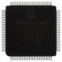
PIC24FJ128GA010-I/PT Microchip Technology, PIC24FJ128GA010-I/PT Datasheet - Page 161

PIC24FJ128GA010-I/PT
Manufacturer Part Number
PIC24FJ128GA010-I/PT
Description
IC PIC MCU FLASH 128K 100TQFP
Manufacturer
Microchip Technology
Series
PIC® 24Fr
Datasheets
1.PIC24FJ16GA002-ISS.pdf
(52 pages)
2.PIC24FJ64GA006-IPT.pdf
(240 pages)
3.PIC24FJ64GA006-IPT.pdf
(22 pages)
4.PIC24FJ128GA008-IPT.pdf
(12 pages)
5.PIC24FJ128GA006-IPT.pdf
(231 pages)
6.PIC24FJ128GA010-IPT.pdf
(230 pages)
Specifications of PIC24FJ128GA010-I/PT
Core Size
16-Bit
Program Memory Size
128KB (43K x 24)
Core Processor
PIC
Speed
16MHz
Connectivity
I²C, PMP, SPI, UART/USART
Peripherals
Brown-out Detect/Reset, POR, PWM, WDT
Number Of I /o
84
Program Memory Type
FLASH
Ram Size
8K x 8
Voltage - Supply (vcc/vdd)
2 V ~ 3.6 V
Data Converters
A/D 16x10b
Oscillator Type
Internal
Operating Temperature
-40°C ~ 85°C
Package / Case
100-TFQFP
Controller Family/series
PIC24
No. Of I/o's
84
Ram Memory Size
8KB
Cpu Speed
32MHz
No. Of Timers
5
No. Of Pwm Channels
5
Embedded Interface Type
EUART, I2C, PSP, SPI
Rohs Compliant
Yes
Processor Series
PIC24FJ
Core
PIC
Data Bus Width
16 bit
Data Ram Size
8 KB
Interface Type
SPI, I2C, USART
Maximum Clock Frequency
16 MHz
Number Of Programmable I/os
54
Number Of Timers
5
Maximum Operating Temperature
+ 85 C
Mounting Style
SMD/SMT
3rd Party Development Tools
52713-733, 52714-737, 53276-922, EWDSPIC
Development Tools By Supplier
PG164130, DV164035, DV244005, DV164005, PG164120, DM240001, DM240011
Minimum Operating Temperature
- 40 C
On-chip Adc
10 bit, 16 Channel
Package
100TQFP
Device Core
PIC
Family Name
PIC24
Maximum Speed
16 MHz
Operating Supply Voltage
2.5|3.3 V
Lead Free Status / RoHS Status
Lead free / RoHS Compliant
For Use With
DM240011 - KIT STARTER MPLAB FOR PIC24F MCUAC164333 - MODULE SKT FOR PM3 100QFPDV164033 - KIT START EXPLORER 16 MPLAB ICD2MA160011 - DAUGHTER BOARD PICDEM LCD 16F91XDM240001 - BOARD DEMO PIC24/DSPIC33/PIC32
Eeprom Size
-
Lead Free Status / Rohs Status
Details
Available stocks
Company
Part Number
Manufacturer
Quantity
Price
Company:
Part Number:
PIC24FJ128GA010-I/PT
Manufacturer:
Microchi
Quantity:
627
Company:
Part Number:
PIC24FJ128GA010-I/PT
Manufacturer:
MICROCHIP
Quantity:
212
Company:
Part Number:
PIC24FJ128GA010-I/PT
Manufacturer:
Microchip Technology
Quantity:
10 000
18.3
• Configurable from half second to one year
• Enabled using the ALRMEN bit (ALCFGRPT<7>,
• One-time alarm and repeat alarm options
18.3.1
The alarm feature is enabled using the ALRMEN bit.
This bit is cleared when an alarm is issued. Writes to
ALRMVALH:ALRMVALL should only take place when
ALRMEN = 0.
As shown in Figure 18-2, the interval selection of the
alarm is configured through the AMASK bits
(ALCFGRPT<13:10>). These bits determine which and
how many digits of the alarm must match the clock
value for the alarm to occur. The alarm can also be con-
figured to repeat based on a preconfigured interval.
The amount of times this occurs once the alarm is
enabled is stored in the lower half of the ALCFGRPT
register.
When ALCFGRPT = 00 and CHIME bit = 0
(ALCFGRPT<14>), the repeat function is disabled and
only a single alarm will occur. The alarm can be
repeated up to 255 times by loading the lower half of
the ALCFGRPT register with FFh.
FIGURE 18-2:
© 2005 Microchip Technology Inc.
Register 18-3)
available
Alarm
Note 1:
0000 – Every half second
0001 – Every second
0010 – Every 10 seconds
0011 – Every minute
0100 – Every 10 minutes
0101 – Every hour
0110 – Every day
0111 – Every week
1000 – Every month
1001 – Every year
CONFIGURING THE ALARM
(AMASK3:AMASK0)
Alarm Mask Setting
Annually, except when configured for February 29.
ALARM MASK SETTINGS
(1)
Advance Information
Day of
Week
the
d
Month
m
PIC24FJ128GA FAMILY
m
After each alarm is issued, the ALCFGRPT register is
decremented by one. Once the register has reached
‘00’, the alarm will be issued one last time, after which
the ALRMEN bit will be cleared automatically and the
alarm will turn off. Indefinite repetition of the alarm can
occur if the CHIME bit = 1. Instead of the alarm being
disabled when the ALCFGRPT register reaches ‘00’, it
will roll over to FF and continue counting indefinitely
when CHIME = 1.
18.3.2
At every alarm event an interrupt is generated. In addi-
tion, an alarm pulse output is provided that operates at
half the frequency of the alarm. This output is
completely synchronous to the RTCC clock and can be
used as a trigger clock to other peripherals.
Note:
d
d
Day
d
d
ALARM INTERRUPT
Changing any of the registers, other then
the RCFGCAL and ALCFGRPT registers
and the CHIME bit while the alarm is
enabled (ALRMEN = 1), can result in a
false alarm event leading to a false alarm
interrupt. To avoid a false alarm event, the
timer and alarm values should only be
changed while the alarm is disabled
(ALRMEN = 0). It is recommended that the
ALCFGRPT register and CHIME bit be
changed when RTCSYNC = 0.
Hours
h
h
h
h
h
h
h
h
Minutes
m
m
m
m
m
m
m
m
m
m
m
DS39747A-page 159
Seconds
s
s
s
s
s
s
s
s
s
s
s
s
s
s
s


