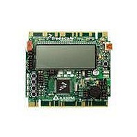
TWR-S08LH64 Freescale Semiconductor, TWR-S08LH64 Datasheet - Page 9

TWR-S08LH64
Manufacturer Part Number
TWR-S08LH64
Description
TOWER SYSTEM S08LH64
Manufacturer
Freescale Semiconductor
Type
MCUr
Datasheets
1.TWR-SENSOR-PAK.pdf
(4 pages)
2.TWR-S08LH64.pdf
(2 pages)
3.TWR-S08LH64.pdf
(19 pages)
4.TWR-S08LH64.pdf
(8 pages)
5.TWR-S08LH64.pdf
(3 pages)
Specifications of TWR-S08LH64
Contents
Board
Description/function
Tower System LCD Module
Interface Type
USB
Backlighting
No Backlighting
Data Bus Width
8 bit
Module Size (w X H X T)
3.55 in x 3.2 in
Number Of Segments
2 x 28
Operating Supply Voltage
5 V
Operating Voltage
3.3 V
Product
Display Modules
Software
Software Included
Touch Panel
No Touch Panel
Silicon Manufacturer
Freescale
Core Architecture
HCS08
Core Sub-architecture
HCS08
Silicon Core Number
MC9S08
Silicon Family Name
S08LH
Kit Contents
Board, Cable, CD
Rohs Compliant
Yes
For Use With/related Products
Freescale Tower System
Lead Free Status / RoHS Status
Lead free / RoHS Compliant
T W R - S 0 8 L L / L H
U S E R
Figure 2: V_SEL Option Header, JP8
Power from the integrated BDM is drawn from the USB bus and is limited to 500 mA total.
This current limit accounts for the total current supplied over the USB cable to the BDM circuit,
the target board, and any connected circuitry. Current drain in excess of 500 mA violates the
USB specification and causes the USB bus to disconnect the offending device. This may
cause the board to exhibit power cycling where the board appears to turn on then off
continually. In this case, LED400 will flash on and off. If this condition is allowed to persist,
damage to the host PC or the target board result.
The on-board voltage regulator (VR1) creates the +3.3V rails used by the target MCU from the
+5V input provided by the OSBDM.
The battery holder at BATT accepts a 3.3V, 23mm, 190mAH lithium, coin-cell battery, PN CR-
2325.
VDD_EN
The VDD_EN option header enables and disables VDD to the target board peripherals. Power
to the MCU is unaffected by this option jumper. Removing this option jumper, along with
others, allows the user to take accurate MCU current measurements. The figure below shows
the VDD_EN option jumper connections.
Figure 3: VDD_EN Option Header, JP9
RESET SWITCH
The RESET switch applies an asynchronous RESET to the MCU. The RESET switch is
connected directly to the RESET* input on the MCU. Pressing the RESET switch applies a
low voltage level to the RESET* input. A pull-up bias resistor allows normal MCU operation.
Shunt capacitance ensures an adequate input pulse width.
(*) – Default Position
G U I D E
VR1
BATT
VR1
BATT
JP9
U S E R
Enables voltage input from on-board regulator. This option should be selected when
powered from the integrated OSBDM (default)
Enables voltage input from battery holder. This option should be selected when
battery-powered operation is desired
G U I D E
Enabled (*)
ON
Disabled
OFF
9
A P R I L
2 7 ,
2 0 1 0


