TWR-S08LH64 Freescale Semiconductor, TWR-S08LH64 Datasheet - Page 7
TWR-S08LH64
Manufacturer Part Number
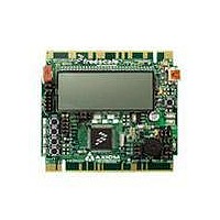
TWR-S08LH64
Description
TOWER SYSTEM S08LH64
Manufacturer
Freescale Semiconductor
Type
MCUr
Datasheets
1.TWR-SENSOR-PAK.pdf
(4 pages)
2.TWR-S08LH64.pdf
(2 pages)
3.TWR-S08LH64.pdf
(19 pages)
4.TWR-S08LH64.pdf
(8 pages)
5.TWR-S08LH64.pdf
(3 pages)
Specifications of TWR-S08LH64
Contents
Board
Description/function
Tower System LCD Module
Interface Type
USB
Backlighting
No Backlighting
Data Bus Width
8 bit
Module Size (w X H X T)
3.55 in x 3.2 in
Number Of Segments
2 x 28
Operating Supply Voltage
5 V
Operating Voltage
3.3 V
Product
Display Modules
Software
Software Included
Touch Panel
No Touch Panel
Silicon Manufacturer
Freescale
Core Architecture
HCS08
Core Sub-architecture
HCS08
Silicon Core Number
MC9S08
Silicon Family Name
S08LH
Kit Contents
Board, Cable, CD
Rohs Compliant
Yes
For Use With/related Products
Freescale Tower System
Lead Free Status / RoHS Status
Lead free / RoHS Compliant


U S E R
OSBDM Bootloader
The OSBDM is pre-programmed with a bootloader application to allow field updates. The USB
bootloader communicates with a GUI application running on a host PC. The GUI application
enables OSBDM firmware to be updated at any. Option jumper JP400 enables the bootloader
at startup. Option header JP400 is not populated in default configuration. Refer to Freescale
Application Note
application note may be found at
BDM_PORT Header
A compatible HCS12 BDM cable can also be attached to the 6-pin BDM interface header at
J400. This header is not installed in default configurations. This header is provide to allow the
use of alternate programming/debug cables. Refer to the external programming/debug cable
documentation for details on use.
The figure below shows the pin-out for the DEBUG header. This information is included for
completeness.
Figure 1: BDM_PORT Header, J400
EXTERNAL BDM CABLE
The integrated BDM allows the user to simply and quickly develop and debug application code.
A BDM port header location is provided for use of an external BDM cable if desired. However,
this BDM port header is not populated in default configurations. Use of an external BDM cable
requires the user to install 6-pin header and to remove a 0-ohm resistor. The user must also
provide power to the board unless power is provided through the external BDM cable. The
P&E Multilink BDM cable used most often with Freescale microprocessors does not provide
power to the target board.
G U I D E
NOTE: This header is not installed in default configuration.
allowable current drain. Damage to the target board or host PC may result
BKGD 1
When powered from the USB bus, do not exceed the 500mA maximum
3
5
J400
AN3561
2 GND
4 RESET*
6 VDD
for details on using the GUI application and bootloader.
www.freescale.com
See the associated RM for complete DEBUG
documentation
CAUTION:
7
or at www.axman.com/support.
The
Related parts for TWR-S08LH64
Image
Part Number
Description
Manufacturer
Datasheet
Request
R

Part Number:
Description:
Development Boards & Kits - S08 / S12 S08PT60 Tower Kit
Manufacturer:
Freescale Semiconductor
Datasheet:
Part Number:
Description:
Development Boards & Kits - S08 / S12 S08PT60Tower MCU mod
Manufacturer:
Freescale Semiconductor
Datasheet:
Part Number:
Description:
TOWER UNIVERSAL RS08/S08
Manufacturer:
Freescale Semiconductor
Datasheet:
Part Number:
Description:
K53N512CMD100 TWR Module
Manufacturer:
Freescale Semiconductor
Datasheet:
Part Number:
Description:
TWR-K53N512 Dev Kit
Manufacturer:
Freescale Semiconductor
Datasheet:

Part Number:
Description:
CONV DC/DC TRI OUT 5,15,-15V
Manufacturer:
Murata Power Solutions Inc
Datasheet:

Part Number:
Description:
CONV DC/DC TRI OUT 5,12,-12V
Manufacturer:
Murata Power Solutions Inc
Datasheet:

Part Number:
Description:
CONV DC/DC TRI OUT 5,15,-15V
Manufacturer:
Murata Power Solutions Inc
Datasheet:

Part Number:
Description:
LCD MODULE FOR TWR SYSTEM
Manufacturer:
Freescale Semiconductor
Datasheet:

Part Number:
Description:
DC/DC TH 11W 5-5/12V Triple A
Manufacturer:
Murata Power Solutions Inc
Datasheet:


Part Number:
Description:
TOWER SYSTEM PROTO
Manufacturer:
Freescale Semiconductor
Datasheet:

Part Number:
Description:
TOWER ELEVATOR BOARDS HARDWARE
Manufacturer:
Freescale Semiconductor
Datasheet: