TWR-S08LH64 Freescale Semiconductor, TWR-S08LH64 Datasheet - Page 13
TWR-S08LH64
Manufacturer Part Number
TWR-S08LH64
Description
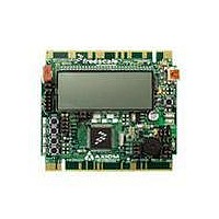
TOWER SYSTEM S08LH64
Manufacturer
Freescale Semiconductor
Type
MCUr
Datasheets
1.TWR-SENSOR-PAK.pdf
(4 pages)
2.TWR-S08LH64.pdf
(2 pages)
3.TWR-S08LH64.pdf
(19 pages)
4.TWR-S08LH64.pdf
(8 pages)
5.TWR-S08LH64.pdf
(3 pages)
Specifications of TWR-S08LH64
Contents
Board
Description/function
Tower System LCD Module
Interface Type
USB
Backlighting
No Backlighting
Data Bus Width
8 bit
Module Size (w X H X T)
3.55 in x 3.2 in
Number Of Segments
2 x 28
Operating Supply Voltage
5 V
Operating Voltage
3.3 V
Product
Display Modules
Software
Software Included
Touch Panel
No Touch Panel
Silicon Manufacturer
Freescale
Core Architecture
HCS08
Core Sub-architecture
HCS08
Silicon Core Number
MC9S08
Silicon Family Name
S08LH
Kit Contents
Board, Cable, CD
Rohs Compliant
Yes
For Use With/related Products
Freescale Tower System
Lead Free Status / RoHS Status
Lead free / RoHS Compliant


T W R - S 0 8 L L / L H
U S E R
VDD1 Enable
The VDD1 option jumper disconnects the BUZZER, and Light sensor from board power for
low-power operation. Figure 9: below shows the option header settings for use with the
VDD1_EN
Buzzer
The TWR-S08 board provides an externally modulated piezo-buzzer for audible applications.
A push-pull drive circuit allows the target MCU to easily drive the buzzer at a center frequency
of 2400 Hz. Figure 9: below shows the option header settings for use with the buzzer.
Light Sensor
A surface-mount phototransistor, at RZ1, provides light sensitive, variable input for user
applications. Current flow within the phototransistor is inversely proportional to light intensity
incident on the surface of the device. A rail-to-rail OP amp at U5 boosts the photocell output to
useable levels. Figure 9: below shows the option header settings for use with the light sensor
Figure 9: USER1 Option Header, JP7
Pushbutton Switches
The TWR-S08 applies 4, normally open, push-button switches for user input. Each push-
button switch is configured for active-low operation. A 22pF capacitor is applied to each push-
button switch to minimize switch bounce. An external pull-up is applied to SW4 for use as and
IRQ* input; however, no bias is applied to the remaining push-button inputs. Use of target
MCU internal pull-ups is required for proper operation.
Figure 10 below shows the user switch connections to the target MCU. Since each push-
button switch is normally-open, no option header is applied.
(*) – Default Position
G U I D E
JP7
SW1 and RZ1 share a common MCU signal input. If both components are
Buzzer
RZ1
VDD1
enabled at the same time, SW 1 may not function properly.
U S E R
G U I D E
Signal
PTC2/TPM1CH0
PTA6/ADP6
VDD
CAUTION:
13
Enabled (*)
Enabled (*)
Enabled (*)
ON
Disabled
Disabled
Disabled
OFF
A P R I L
2 7 ,
2 0 1 0
Related parts for TWR-S08LH64
Image
Part Number
Description
Manufacturer
Datasheet
Request
R

Part Number:
Description:
Development Boards & Kits - S08 / S12 S08PT60 Tower Kit
Manufacturer:
Freescale Semiconductor
Datasheet:
Part Number:
Description:
Development Boards & Kits - S08 / S12 S08PT60Tower MCU mod
Manufacturer:
Freescale Semiconductor
Datasheet:
Part Number:
Description:
TOWER UNIVERSAL RS08/S08
Manufacturer:
Freescale Semiconductor
Datasheet:
Part Number:
Description:
K53N512CMD100 TWR Module
Manufacturer:
Freescale Semiconductor
Datasheet:
Part Number:
Description:
TWR-K53N512 Dev Kit
Manufacturer:
Freescale Semiconductor
Datasheet:

Part Number:
Description:
CONV DC/DC TRI OUT 5,15,-15V
Manufacturer:
Murata Power Solutions Inc
Datasheet:

Part Number:
Description:
CONV DC/DC TRI OUT 5,12,-12V
Manufacturer:
Murata Power Solutions Inc
Datasheet:

Part Number:
Description:
CONV DC/DC TRI OUT 5,15,-15V
Manufacturer:
Murata Power Solutions Inc
Datasheet:

Part Number:
Description:
LCD MODULE FOR TWR SYSTEM
Manufacturer:
Freescale Semiconductor
Datasheet:

Part Number:
Description:
DC/DC TH 11W 5-5/12V Triple A
Manufacturer:
Murata Power Solutions Inc
Datasheet:


Part Number:
Description:
TOWER SYSTEM PROTO
Manufacturer:
Freescale Semiconductor
Datasheet:

Part Number:
Description:
TOWER ELEVATOR BOARDS HARDWARE
Manufacturer:
Freescale Semiconductor
Datasheet: