TWR-S08LH64 Freescale Semiconductor, TWR-S08LH64 Datasheet - Page 15
TWR-S08LH64
Manufacturer Part Number
TWR-S08LH64
Description
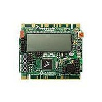
TOWER SYSTEM S08LH64
Manufacturer
Freescale Semiconductor
Type
MCUr
Datasheets
1.TWR-SENSOR-PAK.pdf
(4 pages)
2.TWR-S08LH64.pdf
(2 pages)
3.TWR-S08LH64.pdf
(19 pages)
4.TWR-S08LH64.pdf
(8 pages)
5.TWR-S08LH64.pdf
(3 pages)
Specifications of TWR-S08LH64
Contents
Board
Description/function
Tower System LCD Module
Interface Type
USB
Backlighting
No Backlighting
Data Bus Width
8 bit
Module Size (w X H X T)
3.55 in x 3.2 in
Number Of Segments
2 x 28
Operating Supply Voltage
5 V
Operating Voltage
3.3 V
Product
Display Modules
Software
Software Included
Touch Panel
No Touch Panel
Silicon Manufacturer
Freescale
Core Architecture
HCS08
Core Sub-architecture
HCS08
Silicon Core Number
MC9S08
Silicon Family Name
S08LH
Kit Contents
Board, Cable, CD
Rohs Compliant
Yes
For Use With/related Products
Freescale Tower System
Lead Free Status / RoHS Status
Lead free / RoHS Compliant


T W R - S 0 8 L L / L H
U S E R
Differential ADC Input
The TWR-S08LH64 board provides a differential ADC input to the MC9S08LH64. Option
header JP10 allows the user to route the output and feedback from the Light Sensor (RZ1) to
the MC9S08LH64 differential ADC input. To use this feature correctly, the user should remove
the RZ1 jumper at JP7.
This option header is not populated on the TWR-S08LL version of this board. Figure 13 below
shows the USER2 enable position and associated signal for each user LED.
Figure 13: Option Header, JP10
EDGE CONNECTOR PIN-OUT
The TWR-S08 board connects to the Freescale Tower System using the 2 PCIe Edge
Connectors. Note that according to the PCIe specification, the Bx signals are located on the
top of the board and the Ax signals are located on bottom. Pin B1 for the primary and
secondary connectors are at opposite ends of the board. The figures below show the pin-out
of each edge connector.
The primary connector is located on the side opposite the LCD. Edge connector positions with
no signal name are not connected.
Figure 14: Primary Edge Connector, J1
(*) – Default Position
G U I D E
Differential input signals ADP0 & ADP0_J1 (refer to schematic) are shorted
Elevator Power Sense
U S E R
PTB6/RxD2/SPSCK
RZ1
J1
PTB4/MISO/SDA
PTB5/MOSI/SCL
PTB7/TXD2/SS
5.0V Power
3.3V Power
G U I D E
Ground
Ground
Ground
Connects RZ1 output to MCU (default)
Connects edge connector to MCU
Pri_B01
Pri_B02
Pri_B03
Pri_B04
Pri_B05
Pri_B06
Pri_B07
Pri_B08
Pri_B09
Pri_B10
Pri_B11
on Rev B boards.
NOTE:
15
Pri_A01
Pri_A02
Pri_A03
Pri_A04
Pri_A05
Pri_A06
Pri_A07
Pri_A08
Pri_A09
Pri_A10
Pri_A11
5.0V Power
Ground
3.3V Power
3.3V Power
Ground
Ground
PTB5/MOSI/SCL
PTB4/MISO/SDA
A P R I L
2 7 ,
2 0 1 0
Related parts for TWR-S08LH64
Image
Part Number
Description
Manufacturer
Datasheet
Request
R

Part Number:
Description:
Development Boards & Kits - S08 / S12 S08PT60 Tower Kit
Manufacturer:
Freescale Semiconductor
Datasheet:
Part Number:
Description:
Development Boards & Kits - S08 / S12 S08PT60Tower MCU mod
Manufacturer:
Freescale Semiconductor
Datasheet:
Part Number:
Description:
TOWER UNIVERSAL RS08/S08
Manufacturer:
Freescale Semiconductor
Datasheet:
Part Number:
Description:
K53N512CMD100 TWR Module
Manufacturer:
Freescale Semiconductor
Datasheet:
Part Number:
Description:
TWR-K53N512 Dev Kit
Manufacturer:
Freescale Semiconductor
Datasheet:

Part Number:
Description:
CONV DC/DC TRI OUT 5,15,-15V
Manufacturer:
Murata Power Solutions Inc
Datasheet:

Part Number:
Description:
CONV DC/DC TRI OUT 5,12,-12V
Manufacturer:
Murata Power Solutions Inc
Datasheet:

Part Number:
Description:
CONV DC/DC TRI OUT 5,15,-15V
Manufacturer:
Murata Power Solutions Inc
Datasheet:

Part Number:
Description:
LCD MODULE FOR TWR SYSTEM
Manufacturer:
Freescale Semiconductor
Datasheet:

Part Number:
Description:
DC/DC TH 11W 5-5/12V Triple A
Manufacturer:
Murata Power Solutions Inc
Datasheet:


Part Number:
Description:
TOWER SYSTEM PROTO
Manufacturer:
Freescale Semiconductor
Datasheet:

Part Number:
Description:
TOWER ELEVATOR BOARDS HARDWARE
Manufacturer:
Freescale Semiconductor
Datasheet: