TWR-S08LH64 Freescale Semiconductor, TWR-S08LH64 Datasheet - Page 3
TWR-S08LH64
Manufacturer Part Number
TWR-S08LH64
Description
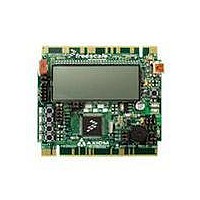
TOWER SYSTEM S08LH64
Manufacturer
Freescale Semiconductor
Type
MCUr
Datasheets
1.TWR-SENSOR-PAK.pdf
(4 pages)
2.TWR-S08LH64.pdf
(2 pages)
3.TWR-S08LH64.pdf
(19 pages)
4.TWR-S08LH64.pdf
(8 pages)
5.TWR-S08LH64.pdf
(3 pages)
Specifications of TWR-S08LH64
Contents
Board
Description/function
Tower System LCD Module
Interface Type
USB
Backlighting
No Backlighting
Data Bus Width
8 bit
Module Size (w X H X T)
3.55 in x 3.2 in
Number Of Segments
2 x 28
Operating Supply Voltage
5 V
Operating Voltage
3.3 V
Product
Display Modules
Software
Software Included
Touch Panel
No Touch Panel
Silicon Manufacturer
Freescale
Core Architecture
HCS08
Core Sub-architecture
HCS08
Silicon Core Number
MC9S08
Silicon Family Name
S08LH
Kit Contents
Board, Cable, CD
Rohs Compliant
Yes
For Use With/related Products
Freescale Tower System
Lead Free Status / RoHS Status
Lead free / RoHS Compliant


T W R - S 0 8 L L / L H
U S E R
Figure 1: BDM_PORT Header, J400 .......................................................................................... 7
Figure 2: V_SEL Option Header, JP8 ......................................................................................... 9
Figure 3: VDD_EN Option Header, JP9...................................................................................... 9
Figure 4: COM Signal Connections .......................................................................................... 10
Figure 5: COM_PORT Connector, J3 ....................................................................................... 11
Figure 6: COM_SEL Option Header, JP5 ................................................................................. 11
Figure 7: Accelerometer Sensitivity Select , JP6 ...................................................................... 12
Figure 8: Accelerometer Output Cut-Traces ............................................................................. 12
Figure 9: USER1 Option Header, JP7 ...................................................................................... 13
Figure 10: Pushbutton Switch Signal Connections ................................................................... 14
Figure 11: USER2 Option Header, JP11 .................................................................................. 14
Figure 12: POT Enable Option Header, JP12 ........................................................................... 14
Figure 13: Option Header, JP10 ............................................................................................... 15
Figure 14: Primary Edge Connector, J1................................................................................... 15
Figure 15: Secondary Edge Connector, J2 ............................................................................... 17
October 5, 2009
October 6, 2009
October 7, 2009
March 23, 2010
April 1, 2010
April 27, 2010
G U I D E
Date
U S E R
G U I D E
Rev
A
B
C
D
E
F
Initial Release
Updated board name to TWR-S08 thru-out
Updated References section to correct document names and remove
Support CD. Updated Figures to show board reference designators
Removed References section.
Added Differential ADC input section. Updated document format
Added External BDM Cable section
REVISION
FIGURES
3
Comments
A P R I L
2 7 ,
2 0 1 0
Related parts for TWR-S08LH64
Image
Part Number
Description
Manufacturer
Datasheet
Request
R

Part Number:
Description:
Development Boards & Kits - S08 / S12 S08PT60 Tower Kit
Manufacturer:
Freescale Semiconductor
Datasheet:
Part Number:
Description:
Development Boards & Kits - S08 / S12 S08PT60Tower MCU mod
Manufacturer:
Freescale Semiconductor
Datasheet:
Part Number:
Description:
TOWER UNIVERSAL RS08/S08
Manufacturer:
Freescale Semiconductor
Datasheet:
Part Number:
Description:
K53N512CMD100 TWR Module
Manufacturer:
Freescale Semiconductor
Datasheet:
Part Number:
Description:
TWR-K53N512 Dev Kit
Manufacturer:
Freescale Semiconductor
Datasheet:

Part Number:
Description:
CONV DC/DC TRI OUT 5,15,-15V
Manufacturer:
Murata Power Solutions Inc
Datasheet:

Part Number:
Description:
CONV DC/DC TRI OUT 5,12,-12V
Manufacturer:
Murata Power Solutions Inc
Datasheet:

Part Number:
Description:
CONV DC/DC TRI OUT 5,15,-15V
Manufacturer:
Murata Power Solutions Inc
Datasheet:

Part Number:
Description:
LCD MODULE FOR TWR SYSTEM
Manufacturer:
Freescale Semiconductor
Datasheet:

Part Number:
Description:
DC/DC TH 11W 5-5/12V Triple A
Manufacturer:
Murata Power Solutions Inc
Datasheet:


Part Number:
Description:
TOWER SYSTEM PROTO
Manufacturer:
Freescale Semiconductor
Datasheet:

Part Number:
Description:
TOWER ELEVATOR BOARDS HARDWARE
Manufacturer:
Freescale Semiconductor
Datasheet: