TWR-S08LH64 Freescale Semiconductor, TWR-S08LH64 Datasheet - Page 8
TWR-S08LH64
Manufacturer Part Number
TWR-S08LH64
Description
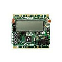
TOWER SYSTEM S08LH64
Manufacturer
Freescale Semiconductor
Type
MCUr
Datasheets
1.TWR-SENSOR-PAK.pdf
(4 pages)
2.TWR-S08LH64.pdf
(2 pages)
3.TWR-S08LH64.pdf
(19 pages)
4.TWR-S08LH64.pdf
(8 pages)
5.TWR-S08LH64.pdf
(3 pages)
Specifications of TWR-S08LH64
Contents
Board
Description/function
Tower System LCD Module
Interface Type
USB
Backlighting
No Backlighting
Data Bus Width
8 bit
Module Size (w X H X T)
3.55 in x 3.2 in
Number Of Segments
2 x 28
Operating Supply Voltage
5 V
Operating Voltage
3.3 V
Product
Display Modules
Software
Software Included
Touch Panel
No Touch Panel
Silicon Manufacturer
Freescale
Core Architecture
HCS08
Core Sub-architecture
HCS08
Silicon Core Number
MC9S08
Silicon Family Name
S08LH
Kit Contents
Board, Cable, CD
Rohs Compliant
Yes
For Use With/related Products
Freescale Tower System
Lead Free Status / RoHS Status
Lead free / RoHS Compliant


T W R - S 0 8 L L / L H
U S E R
To use an external BDM cable, the user must install a header at location J400. A resistor at
R411 must also be removed to prevent contention between the external BDM cable and the
OSBDM.
To use an external BDM, the user must also apply power to the board. Power may be applied
through the OSBDM or at the COM header. Simply connecting the USB cable to the USB
connector will apply power to the board.
connector at J3. Apply +3.3VDC at J3-10 and GND at J3-9. Please note that no over-voltage
or transient protection is applied at this power input.
The external BDM is now ready for use.
POWER
The TWR-S08 board may be powered from the OSBDM or from the Tower System.
190mAH battery holder is applied for battery-powered operation. The USB current limit must
be observed while using the USB connection from the host PC to supply power to the target
board. Damage to the target board, Tower System, or host PC may otherwise occur.
POWER SELECT
Option headers V_SEL and VDD_EN select the source of input power to the target board.
When powered from the Tower System, the OSBDM voltage output is disabled.
V_SEL
The V_SEL option header allows the user to select power input either the on-board regulator
or the battery holder. The on-board regulator is supplied from the OSBDM voltage output.
Figure 2 below shows the PWR_SEL header settings.
G U I D E
Do not apply power to COM connector J3 while also powering the board
Do not apply excessive voltage at input J3-9 and J3-10. Neither over-
U S E R
through the OSBDM. Damage to the board may result.
voltage nor transient protection is applied at this input.
G U I D E
CAUTION:
CAUTION:
The user may also apply power to the COM
8
A P R I L
2 7 ,
2 0 1 0
A
Related parts for TWR-S08LH64
Image
Part Number
Description
Manufacturer
Datasheet
Request
R

Part Number:
Description:
Development Boards & Kits - S08 / S12 S08PT60 Tower Kit
Manufacturer:
Freescale Semiconductor
Datasheet:
Part Number:
Description:
Development Boards & Kits - S08 / S12 S08PT60Tower MCU mod
Manufacturer:
Freescale Semiconductor
Datasheet:
Part Number:
Description:
TOWER UNIVERSAL RS08/S08
Manufacturer:
Freescale Semiconductor
Datasheet:
Part Number:
Description:
K53N512CMD100 TWR Module
Manufacturer:
Freescale Semiconductor
Datasheet:
Part Number:
Description:
TWR-K53N512 Dev Kit
Manufacturer:
Freescale Semiconductor
Datasheet:

Part Number:
Description:
CONV DC/DC TRI OUT 5,15,-15V
Manufacturer:
Murata Power Solutions Inc
Datasheet:

Part Number:
Description:
CONV DC/DC TRI OUT 5,12,-12V
Manufacturer:
Murata Power Solutions Inc
Datasheet:

Part Number:
Description:
CONV DC/DC TRI OUT 5,15,-15V
Manufacturer:
Murata Power Solutions Inc
Datasheet:

Part Number:
Description:
LCD MODULE FOR TWR SYSTEM
Manufacturer:
Freescale Semiconductor
Datasheet:

Part Number:
Description:
DC/DC TH 11W 5-5/12V Triple A
Manufacturer:
Murata Power Solutions Inc
Datasheet:


Part Number:
Description:
TOWER SYSTEM PROTO
Manufacturer:
Freescale Semiconductor
Datasheet:

Part Number:
Description:
TOWER ELEVATOR BOARDS HARDWARE
Manufacturer:
Freescale Semiconductor
Datasheet: