TWR-S08LH64 Freescale Semiconductor, TWR-S08LH64 Datasheet - Page 10
TWR-S08LH64
Manufacturer Part Number
TWR-S08LH64
Description
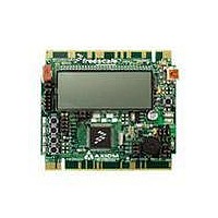
TOWER SYSTEM S08LH64
Manufacturer
Freescale Semiconductor
Type
MCUr
Datasheets
1.TWR-SENSOR-PAK.pdf
(4 pages)
2.TWR-S08LH64.pdf
(2 pages)
3.TWR-S08LH64.pdf
(19 pages)
4.TWR-S08LH64.pdf
(8 pages)
5.TWR-S08LH64.pdf
(3 pages)
Specifications of TWR-S08LH64
Contents
Board
Description/function
Tower System LCD Module
Interface Type
USB
Backlighting
No Backlighting
Data Bus Width
8 bit
Module Size (w X H X T)
3.55 in x 3.2 in
Number Of Segments
2 x 28
Operating Supply Voltage
5 V
Operating Voltage
3.3 V
Product
Display Modules
Software
Software Included
Touch Panel
No Touch Panel
Silicon Manufacturer
Freescale
Core Architecture
HCS08
Core Sub-architecture
HCS08
Silicon Core Number
MC9S08
Silicon Family Name
S08LH
Kit Contents
Board, Cable, CD
Rohs Compliant
Yes
For Use With/related Products
Freescale Tower System
Lead Free Status / RoHS Status
Lead free / RoHS Compliant


T W R - S 0 8 L L / L H
U S E R
LOW VOLTAGE RESET
The target MCU applies an internal Low Voltage Detect (LVD) circuit. The LVD holds the MCU
in reset until applied voltage reaches an appropriate level. The LVD also protect against
under-voltage conditions. Consult the target device RM for details on LVD operation.
TIMING
The TWR-S08 uses the MC9S08LL or MC9S08LH internal timing source by default.
external 32 kHz XTAL oscillator, configured for low-power operation, is also provided. Consult
the target device RM for details on configuring the selected timing source.
COMMUNICATIONS
The TWR-S08 board supports serial communications through an on-board, low-voltage, RS-
232 physical layer transceiver (PHY) connected to a 2x5, 0.1”, pin header. The PHY supports
valid RS-232 signaling for input voltage levels down to +1.8V. The COM_SEL header selects
the serial path applied.
RS-232
An RS-232 translator provides RS-232 to TTL/CMOS logic level translation on the COM
connector. The COM_PORT connector is a 2x5, 0.1”, pin header. Communication signals
TXD1 and RXD1 are routed from the transceiver to the MCU. Hardware flow control signals
RTS and CTS are available on the logic side of the transceiver. These signals are routed to
vias located near the transceiver. RTS has been biased properly to support 2-wire RS-232
communications. Figure 4 below shows the COM signal connections.
Figure 4: COM Signal Connections
G U I D E
However, the OSBDM does not support serial communications at this time.
The COM_SEL header allows the SCI signals to be routed to the OSBDM.
MCU Signal
PTC1/TXD
PTC0RXD
U S E R
G U I D E
COM Signal
TXD
RXD
NOTE:
10
A P R I L
2 7 ,
2 0 1 0
An
Related parts for TWR-S08LH64
Image
Part Number
Description
Manufacturer
Datasheet
Request
R

Part Number:
Description:
Development Boards & Kits - S08 / S12 S08PT60 Tower Kit
Manufacturer:
Freescale Semiconductor
Datasheet:
Part Number:
Description:
Development Boards & Kits - S08 / S12 S08PT60Tower MCU mod
Manufacturer:
Freescale Semiconductor
Datasheet:
Part Number:
Description:
TOWER UNIVERSAL RS08/S08
Manufacturer:
Freescale Semiconductor
Datasheet:
Part Number:
Description:
K53N512CMD100 TWR Module
Manufacturer:
Freescale Semiconductor
Datasheet:
Part Number:
Description:
TWR-K53N512 Dev Kit
Manufacturer:
Freescale Semiconductor
Datasheet:

Part Number:
Description:
CONV DC/DC TRI OUT 5,15,-15V
Manufacturer:
Murata Power Solutions Inc
Datasheet:

Part Number:
Description:
CONV DC/DC TRI OUT 5,12,-12V
Manufacturer:
Murata Power Solutions Inc
Datasheet:

Part Number:
Description:
CONV DC/DC TRI OUT 5,15,-15V
Manufacturer:
Murata Power Solutions Inc
Datasheet:

Part Number:
Description:
LCD MODULE FOR TWR SYSTEM
Manufacturer:
Freescale Semiconductor
Datasheet:

Part Number:
Description:
DC/DC TH 11W 5-5/12V Triple A
Manufacturer:
Murata Power Solutions Inc
Datasheet:


Part Number:
Description:
TOWER SYSTEM PROTO
Manufacturer:
Freescale Semiconductor
Datasheet:

Part Number:
Description:
TOWER ELEVATOR BOARDS HARDWARE
Manufacturer:
Freescale Semiconductor
Datasheet: