CDB4265 Cirrus Logic Inc, CDB4265 Datasheet - Page 31
CDB4265
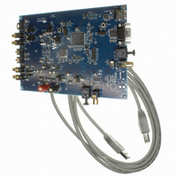
Manufacturer Part Number
CDB4265
Description
BOARD EVAL FOR CS4265 CODEC
Manufacturer
Cirrus Logic Inc
Specifications of CDB4265
Main Purpose
Audio, CODEC
Embedded
No
Utilized Ic / Part
CS4265
Primary Attributes
Stereo, 24-Bit, 192 kHz Sample Rate
Secondary Attributes
Graphic User Interface, S/PDIF/ I2S / I2C / SPI Interface
Description/function
Audio CODECs
Operating Supply Voltage
5 V
Product
Audio Modules
For Use With/related Products
CS4265
Lead Free Status / RoHS Status
Contains lead / RoHS non-compliant
Lead Free Status / RoHS Status
Lead free / RoHS Compliant, Contains lead / RoHS non-compliant
Other names
598-1001


DS657F2
4.14
SCL
SDA
SDA
SCL
START
Since the read operation cannot set the MAP, an aborted write operation is used as a preamble. As shown
in
dition. The following pseudocode illustrates an aborted write operation followed by a read operation.
Send start condition.
Send 100111x0 (chip address & write operation).
Receive acknowledge bit.
Send MAP byte.
Receive acknowledge bit.
Send stop condition, aborting write.
Send start condition.
Send 100111x1(chip address & read operation).
Receive acknowledge bit.
Receive byte, contents of selected register.
Send acknowledge bit.
Send stop condition.
Status Reporting
The CS4265 has comprehensive status reporting capabilities. Many conditions can be reported in the status
register, as listed in the status register descriptions. See
may be masked off through mask register bits. In addition, each source may be set to rising edge, falling
edge, or level sensitive. Combined with the option of level-sensitive or edge-sensitive modes within the mi-
crocontroller, many different configurations are possible, depending on the needs of the equipment design-
er.
Figure
START
0
1
CHIP ADDRESS (WRITE)
1
0
0
0
1
2
CHIP ADDRESS (WRITE)
16, the write operation is aborted after the acknowledge for the MAP byte by sending a stop con-
1
1
0
3
1
2
0
4
1
1
5
3
AD0
6
1
4
7
0
1 AD0 0
5
ACK
8
6
9
7
7
Figure 16. Control Port Timing, I²C Read
10 11
Figure 15. Control Port Timing, I²C Write
6
ACK
8
5
MAP BYTE
9
7
12 13 14 15
4
10 11
6
3
MAP BYTE
5
2
12
4
1
13 14 15
3
16
0
ACK
2
STOP
17 18
START
1
16 17 18
0
19
ACK
1
20 21 22 23 24
CHIP ADDRESS (READ)
0
7
“Status - Address 0Dh” on page
0
19
6
DATA
1
1
24 25
1
1
0
AD0 1
ACK
25
26
26 27 28
27 28
7
ACK
DATA +1
6
7
DATA
1
0
ACK
0
DATA +1
7
7
DATA +n
6
0
42. Each source
1
DATA + n
7
0
ACK
CS4265
0
STOP
ACK
NO
STOP
31
Related parts for CDB4265
Image
Part Number
Description
Manufacturer
Datasheet
Request
R

Part Number:
Description:
Development Kit
Manufacturer:
Cirrus Logic Inc
Datasheet:
Part Number:
Description:
Development Kit
Manufacturer:
Cirrus Logic Inc
Datasheet:


Part Number:
Description:
High-efficiency PFC + Fluorescent Lamp Driver Reference Design
Manufacturer:
Cirrus Logic Inc
Datasheet:
Part Number:
Description:
Development Kit
Manufacturer:
Cirrus Logic Inc
Datasheet:
Part Number:
Description:
Development Kit
Manufacturer:
Cirrus Logic Inc
Datasheet:

Part Number:
Description:
Development Kit
Manufacturer:
Cirrus Logic Inc
Datasheet:
Part Number:
Description:
Development Kit
Manufacturer:
Cirrus Logic Inc
Datasheet:
Part Number:
Description:
Development Kit
Manufacturer:
Cirrus Logic Inc
Datasheet:
Part Number:
Description:
Development Kit
Manufacturer:
Cirrus Logic Inc
Datasheet:

Part Number:
Description:
EVALUATION BOARD FOR CS8427
Manufacturer:
Cirrus Logic Inc
Datasheet:

Part Number:
Description:
BOARD EVAL FOR CS8416 RCVR
Manufacturer:
Cirrus Logic Inc
Datasheet:

Part Number:
Description:
EVALUATION BOARD FOR CS8420
Manufacturer:
Cirrus Logic Inc
Datasheet:

Part Number:
Description:
KIT DEVELOPMENT EP9315 ARM9
Manufacturer:
Cirrus Logic Inc
Datasheet:

Part Number:
Description:
KIT DEVELOPMENT EP9302 ARM9
Manufacturer:
Cirrus Logic Inc
Datasheet: