PTN3700EV/G,118 NXP Semiconductors, PTN3700EV/G,118 Datasheet - Page 28
PTN3700EV/G,118
Manufacturer Part Number
PTN3700EV/G,118
Description
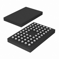
IC MOBILE INTERFACE 56-VFBGA
Manufacturer
NXP Semiconductors
Type
Interfacer
Series
-r
Datasheet
1.PTN3700EVG118.pdf
(41 pages)
Specifications of PTN3700EV/G,118
Package / Case
56-VFBGA
Applications
Mobile Phones, Cellular, Video Displays
Mounting Type
Surface Mount
Input Current
4 uA
Maximum Operating Temperature
+ 85 C
Minimum Operating Temperature
- 40 C
Mounting Style
SMD/SMT
Operating Supply Voltage
1.8 V
Supply Voltage (max)
1.95 V
Supply Voltage (min)
1.65 V
Number Of Outputs
4
Lead Free Status / RoHS Status
Lead free / RoHS Compliant
Lead Free Status / RoHS Status
Lead free / RoHS Compliant, Lead free / RoHS Compliant
Other names
935284074118
PTN3700EV/G-T
PTN3700EV/G-T
PTN3700EV/G-T
PTN3700EV/G-T
Available stocks
Company
Part Number
Manufacturer
Quantity
Price
Company:

Part Number:
PTN3700EV/G,118
Manufacturer:
NXP Semiconductors
Quantity:
10 000


NXP Semiconductors
Table 21.
V
[1]
[2]
[3]
PTN3700_1
Product data sheet
Symbol
V
V
V
R
t
t
f
I
I
t
t
r(dif)
f(dif)
oper
O
LO
bit(CLKH-Q)
sk(CLK-Q)
DD
V
V
t
t
O(dif)
O(cm)
O(cm)ripple(p-p)
o(dif)
r
f
O(dif)
O(cm)
= 1.65 V to 1.95 V, T
Mode 00: UI = PCLK period / 30
Mode 01: UI = PCLK period / 15
Mode 10: UI = PCLK period / 10
N is defined as the bit position, where 0
%
/V
O(dif)
=
High-speed signaling channel SubLVDS output characteristics, Transmitter mode
V
---------------------------------------------------------------- - 100 %
O dif CLK
Parameter
differential output
voltage
common-mode output
voltage
peak-to-peak ripple
common-mode output
voltage
differential output
resistance
differential rise time
differential fall time
operating frequency
output current
relative differential
output voltage
difference
common-mode output
voltage difference
rise time difference
fall time difference
output leakage current
bit time from CLK
HIGH to data output
CLK edge to data
output skew time
11.4 High-speed signaling channel
V
O dif CLK
–
amb
V
O dif DATA
= 40 C to +85 C, unless otherwise specified. See
Conditions
see
see
see
between complimentary outputs of
any differential pair: CLK+/CLK ;
D0+/D0 ; D1+/D1 ; D2+/D2
from 20 % to 80 % of V
see
from 80 % to 20 % of V
see
output drive current per channel
between CLK+/CLK and
Dn+/Dn , referenced to
CLK+/CLK
between CLK+/CLK and
Dn+/Dn
t
t
Shutdown or Standby mode
(high-impedance state)
PSS mode; Mode 00 or Mode 01;
see
PSS mode: Mode 10; see
Table
FSS mode; see
N
r
f
(CLK+/CLK )
(CLK+/CLK )
29 (Mode 00), 0
Figure 26
Figure 26
Figure 27
Figure 28
Figure 28
Table
5,
Figure 31
Rev. 01 — 14 August 2007
5,
Figure 31
Figure 33
t
t
f
r
(Dn+/Dn )
(Dn+/Dn )
N
O(dif)
O(dif)
14 (Mode 01) or 0
;
;
1.8 V simple mobile interface link bridge IC
[2][3]
[2][3]
[1]
[2]
Section 13.1
Min
100
0.8
80
200
200
-
-
N
N
N
75
10
0.1
100
100
3.0
16 %
19 %
16 %
UI
UI
9 (Mode 10).
UI 0
UI
UI
for testing information.
Typ
150
0.9
-
180
-
-
-
-
-
-
-
-
-
N
N
UI N
UI N
PTN3700
© NXP B.V. 2007. All rights reserved.
Max
200
1.0
+75
280
500
500
325
4
+10
+0.1
+100
+100
+3.0
+ 19 %
+ 16 %
+16 %
UI
UI
UI
UI
UI
28 of 41
Unit
mV
V
mV
ps
ps
MHz
mA
%
V
ps
ps
ps
ps
ps
A
Related parts for PTN3700EV/G,118
Image
Part Number
Description
Manufacturer
Datasheet
Request
R

Part Number:
Description:
Serializers & Deserializers - Serdes 1.8V MOBILE INTERF LINK BRIDGE
Manufacturer:
NXP Semiconductors

Part Number:
Description:
1.8 V simple mobile interface link bridge IC Very low power profile
Manufacturer:
NXP [NXP Semiconductors]
Datasheet:
Part Number:
Description:
NXP Semiconductors designed the LPC2420/2460 microcontroller around a 16-bit/32-bitARM7TDMI-S CPU core with real-time debug interfaces that include both JTAG andembedded trace
Manufacturer:
NXP Semiconductors
Datasheet:

Part Number:
Description:
NXP Semiconductors designed the LPC2458 microcontroller around a 16-bit/32-bitARM7TDMI-S CPU core with real-time debug interfaces that include both JTAG andembedded trace
Manufacturer:
NXP Semiconductors
Datasheet:
Part Number:
Description:
NXP Semiconductors designed the LPC2468 microcontroller around a 16-bit/32-bitARM7TDMI-S CPU core with real-time debug interfaces that include both JTAG andembedded trace
Manufacturer:
NXP Semiconductors
Datasheet:
Part Number:
Description:
NXP Semiconductors designed the LPC2470 microcontroller, powered by theARM7TDMI-S core, to be a highly integrated microcontroller for a wide range ofapplications that require advanced communications and high quality graphic displays
Manufacturer:
NXP Semiconductors
Datasheet:
Part Number:
Description:
NXP Semiconductors designed the LPC2478 microcontroller, powered by theARM7TDMI-S core, to be a highly integrated microcontroller for a wide range ofapplications that require advanced communications and high quality graphic displays
Manufacturer:
NXP Semiconductors
Datasheet:
Part Number:
Description:
The Philips Semiconductors XA (eXtended Architecture) family of 16-bit single-chip microcontrollers is powerful enough to easily handle the requirements of high performance embedded applications, yet inexpensive enough to compete in the market for hi
Manufacturer:
NXP Semiconductors
Datasheet:
Part Number:
Description:
The XA-S3 device is a member of Philips Semiconductors? XA(eXtended Architecture) family of high performance 16-bitsingle-chip microcontrollers
Manufacturer:
NXP Semiconductors
Datasheet:

Part Number:
Description:
The NXP BlueStreak LH75401/LH75411 family consists of two low-cost 16/32-bit System-on-Chip (SoC) devices
Manufacturer:
NXP Semiconductors
Datasheet:
Part Number:
Description:
The NXP LPC3130/3131 combine an 180 MHz ARM926EJ-S CPU core, high-speed USB2
Manufacturer:
NXP Semiconductors
Datasheet:
Part Number:
Description:
The NXP LPC3141 combine a 270 MHz ARM926EJ-S CPU core, High-speed USB 2
Manufacturer:
NXP Semiconductors
Part Number:
Description:
The NXP LPC3143 combine a 270 MHz ARM926EJ-S CPU core, High-speed USB 2
Manufacturer:
NXP Semiconductors

Part Number:
Description:
The NXP LPC3152 combines an 180 MHz ARM926EJ-S CPU core, High-speed USB 2
Manufacturer:
NXP Semiconductors