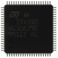
STA310 STMicroelectronics, STA310 Datasheet - Page 9

STA310
Manufacturer Part Number
STA310
Description
IC AUDIO DECODER 6+2CH 80-TQFP
Manufacturer
STMicroelectronics
Type
Audio Decoderr
Datasheet
1.STA310.pdf
(90 pages)
Specifications of STA310
Applications
HDTV, Players, Receivers, Set-Top Boxes
Voltage - Supply, Analog
2.5V
Voltage - Supply, Digital
2.5V
Mounting Type
Surface Mount
Package / Case
80-TQFP, 80-VQFP
Audio Codec Type
MP3 Decoder
No. Of Dacs
3
No. Of Input Channels
2
No. Of Output Channels
6
Adc / Dac Resolution
32bit
Sampling Rate
192kHz
Interface Type
I2C, Serial, Parallel
Rohs Compliant
Yes
Lead Free Status / RoHS Status
Lead free / RoHS Compliant
Other names
497-8856
STA310
STA310
Available stocks
Company
Part Number
Manufacturer
Quantity
Price
Part Number:
STA310
Manufacturer:
ST
Quantity:
20 000
The timing diagrams for the parallel control interface are given in
3.4 I
When the pin SELI2C is high, the chip is controlled through the I²C interface. The I²C unit works at up to 400kHz
in slave mode with 7-bit addressing.
The I²C Bus standard does not specify sub-addressing. There are thus potentially multiple ways to implement
it. Any implementation that respects the standard is of course legal but a particular implementation is used by
many companies. The following paragraphs describe this implementation.
3.4.1 Protocol description
For write accesses only, the first data which follows the slave address is always the sub-address.
This is the one and only way to declare the sub-address. It should be noticed that the sub-address is implement-
ed as a standard data on the I²C Bus protocol point of view. It is a sub-address because the slave knows that it
must load its address pointer with the first data sent by the master.
See in the Appendix X.x for I
3.5 Decoding process
The decoding process in the STA310 is done in several stages:
Each of the stages can be activated or bypassed according to the configuration registers.
Parsing
The bitstream parsing (performed by the input processor) is in charge of discarding all the non audio information
in order to transmit to the next stage (the circular frame buffer) only the audio elementary stream (AC3, MPEG1/
2, LPCM, PCM, DVD Audio).
The parsing stage operates in two phases: the packet parser unpacks the stream, the audio parser checks the
syntax of the bitstream.
Main Decoding
The input of this stage is an elementary stream, the outputs are decoded samples. The number of output chan-
nels is defined by the downmix register (1 channel up to 6 channels). For details, please refer to the description
of the register.
The decoding formats currently supported are AC3, MPEG1 layers I and II, MPEG2 layer II, LPCM. It is neces-
sary to select the appropriate stream format by configuring the registers STREAMSEL and DECODESEL before
running the decoder.
- The signal WAIT. This signal is always driven low in response to the DCSB assertion.
- The Pin MAINI2CADR selects the device address. When MAINI2CADR is high the slave address is
- The pin SDAI2C is the serial data line.
- The pin SCLKI2C is the serial clock.
- Parsing,
- Main decoding,
- Post decoding,
- Bass redirection,
- Volume and Balance control.
0x5C, when low the device address is equal to the value on the address bus (A0...A6).
2
C control interface
2
C message format examples.
Electrical specifications on page
5.
STA310
9/90


