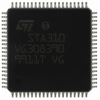
STA310 STMicroelectronics, STA310 Datasheet - Page 8

STA310
Manufacturer Part Number
STA310
Description
IC AUDIO DECODER 6+2CH 80-TQFP
Manufacturer
STMicroelectronics
Type
Audio Decoderr
Datasheet
1.STA310.pdf
(90 pages)
Specifications of STA310
Applications
HDTV, Players, Receivers, Set-Top Boxes
Voltage - Supply, Analog
2.5V
Voltage - Supply, Digital
2.5V
Mounting Type
Surface Mount
Package / Case
80-TQFP, 80-VQFP
Audio Codec Type
MP3 Decoder
No. Of Dacs
3
No. Of Input Channels
2
No. Of Output Channels
6
Adc / Dac Resolution
32bit
Sampling Rate
192kHz
Interface Type
I2C, Serial, Parallel
Rohs Compliant
Yes
Lead Free Status / RoHS Status
Lead free / RoHS Compliant
Other names
497-8856
STA310
STA310
Available stocks
Company
Part Number
Manufacturer
Quantity
Price
Part Number:
STA310
Manufacturer:
ST
Quantity:
20 000
STA310
3.2 Functional diagram
Figure 2. Audio decoder top level functional diagram
3.3 Control interface description
The IC can be controlled either by a host using an I²C interface, or by a general purpose host interface.
These interfaces provide the same functions and are described in the following sections. The selection is per-
formed by the means of the pin SELI2C: when high, this pin indicates that the I²C interface is used. When low,
the parallel interface is used.
3.3.1 Parallel control interface
When the pin SELI2C is low, the control of the chip is performed through the parallel interface. When accessing
the device through the parallel interface, the following signals are used:
Note: 1. The address bus A[7..0], and read/write signal R/W must be setup before the DCSB line is activated.
8/90
MAINI2CADR
- The address bus A[7..0]. It is used to select one of the 256 register locations.
- The data bus DATA[7..0]. If a read cycle is requested, the data lines D[7:0] will be driven by the IC.
- The signal R/W. It defines the type of register access: either read (when high), or write (when low).
- The signal DCSB. A cycle is defined by the assertion of the signal DCSB.
LRCLKIN2
SCLKI2C
LRCLKIN
SDAI2C
DSTRB2
For a write cycle, the STA310 will latch the data placed on the data lines when the WAIT signal is
driven high.
Some registers can be either written or read, some are read only, some are write only.
DSTRB
D[0..7]
DCSB
A[0..7]
REQ2
IRQ
REQ
SIN2
SIN
43
46
53
21
48
41
40
37
42
60
61
62
63
STA310
STA310
CONTROL
I2S_IN1
I2S_IN2
FORMATTER PTS
PACKET
Voice Effects:
Echo,
Chorus
Reverb
BUFFER
FRAME
Sample
Rate
Converter
LPCM
Beep Tone Gen
Pink Noise Gen
video
PCM
MPEG 2
Layer 1-2
MPEG 1
AC-3
CDDA
MLP
MP3
Level Sensitive
Cancel
Gain
6
2
6
2 to 6 ch
2
L/Lt
R/Rt
C
Lfe
Ls
Rs
Downmix Lt/Rt
6
2
2
2/0
2to2
6to2
IEC 1937 (AC-3 / MPEG 2)
1..4
1..6
L
R
C
lfe
Ls
Rs
2
6
RVCR
LVCR
NULL DATA
L
R
C
lfe
Ls
Rs
DELAY
DELAY
DELAY
DELAY
DELAY
DELAY
DELAY
DELAY
Switctch
PCM
System
Clocks
Audio
and
73
63 SCLK
68 LRCLK
64 CLKOUT
31 CLK
69 PCMCLK
58
76
77
72
I958OUT
PCMOUT1
PCMOUT2
PCMOUT3
PCMOUT0


