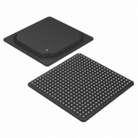
DS33R41+ Maxim Integrated Products, DS33R41+ Datasheet - Page 29

DS33R41+
Manufacturer Part Number
DS33R41+
Description
IC TXRX ETHERNET MAP 400-BGA
Manufacturer
Maxim Integrated Products
Type
Transceiverr
Datasheet
1.DS33R41.pdf
(335 pages)
Specifications of DS33R41+
Number Of Drivers/receivers
4/4
Protocol
T1/E1/J1
Voltage - Supply
3.14 V ~ 3.47 V
Mounting Type
Surface Mount
Package / Case
400-BGA
Lead Free Status / RoHS Status
Lead free / RoHS Compliant
- Current page: 29 of 335
- Download datasheet (2Mb)
RLOS/LOTC1
RLOS/LOTC2
RLOS/LOTC3
RLOS/LOTC4
MODEC[0],
MODEC[1]
TSTRST
NAME
QOVF
TPD
RST
DS33R41 Inverse-Multiplexing Ethernet Mapper with Quad Integrated T1/E1/J1 Transceivers
G15
G18
H15
C14
PIN
E7,
D6
R2
D4
V8
L2
TYPE
O
O
I
I
I
I
HARDWARE AND STATUS PINS
Test/Reset. A dual-function pin. A zero-to-one transition issues a
hardware reset to the transceiver register set. A reset clears all
configuration registers. Configuration register contents are set to zero.
Leaving TSTRST high will tri-state all output and I/O pins (including the
parallel control port). Set low for normal operation. Useful in board-level
testing.
Reset. An active low signal on this pin resets the internal registers and
logic. This pin should remain low until power, SYSCLKI, RX_CLK, and
TX_CLK are stable, then set high for normal operation. This input
requires a clean edge with a rise time of 25ns or less to properly reset the
device.
Transceiver Transmit Power-Down. The TPD pin along with the TPD bit
in the LIC1 register (LIC1.0) controls the state of the Transmit Power-
Down function. See the TPD bit description in Section
Mode Control
00 = Read/Write Strobe Used (Intel Mode)
01 = Data Strobe Used (Motorola Mode)
10 = Reserved. Do not use.
11 = Reserved. Do not use.
Receive Loss of Sync/Loss of Transmit Clock for Transceiver 1. A
dual-function output that is controlled by the TR.CCR1.0 control bit. This
pin can be programmed to either toggle high when the synchronizer is
searching for the frame and multiframe or to toggle high if the TCLKT pin
has not been toggled for 5μs.
Queue Overflow. This pin goes high when the transmit or receive queue
has overflowed. This pin will go low when the high watermark is reached
again.
29 of 335
FUNCTION
12
and
Table
12-9..
Related parts for DS33R41+
Image
Part Number
Description
Manufacturer
Datasheet
Request
R

Part Number:
Description:
MAX7528KCWPMaxim Integrated Products [CMOS Dual 8-Bit Buffered Multiplying DACs]
Manufacturer:
Maxim Integrated Products
Datasheet:

Part Number:
Description:
Single +5V, fully integrated, 1.25Gbps laser diode driver.
Manufacturer:
Maxim Integrated Products
Datasheet:

Part Number:
Description:
Single +5V, fully integrated, 155Mbps laser diode driver.
Manufacturer:
Maxim Integrated Products
Datasheet:

Part Number:
Description:
VRD11/VRD10, K8 Rev F 2/3/4-Phase PWM Controllers with Integrated Dual MOSFET Drivers
Manufacturer:
Maxim Integrated Products
Datasheet:

Part Number:
Description:
Highly Integrated Level 2 SMBus Battery Chargers
Manufacturer:
Maxim Integrated Products
Datasheet:

Part Number:
Description:
Current Monitor and Accumulator with Integrated Sense Resistor; ; Temperature Range: -40°C to +85°C
Manufacturer:
Maxim Integrated Products

Part Number:
Description:
TSSOP 14/A°/RS-485 Transceivers with Integrated 100O/120O Termination Resis
Manufacturer:
Maxim Integrated Products

Part Number:
Description:
TSSOP 14/A°/RS-485 Transceivers with Integrated 100O/120O Termination Resis
Manufacturer:
Maxim Integrated Products

Part Number:
Description:
QFN 16/A°/AC-DC and DC-DC Peak-Current-Mode Converters with Integrated Step
Manufacturer:
Maxim Integrated Products

Part Number:
Description:
TDFN/A/65V, 1A, 600KHZ, SYNCHRONOUS STEP-DOWN REGULATOR WITH INTEGRATED SWI
Manufacturer:
Maxim Integrated Products

Part Number:
Description:
Integrated Temperature Controller f
Manufacturer:
Maxim Integrated Products

Part Number:
Description:
SOT23-6/I°/45MHz to 650MHz, Integrated IF VCOs with Differential Output
Manufacturer:
Maxim Integrated Products

Part Number:
Description:
SOT23-6/I°/45MHz to 650MHz, Integrated IF VCOs with Differential Output
Manufacturer:
Maxim Integrated Products

Part Number:
Description:
EVALUATION KIT/2.4GHZ TO 2.5GHZ 802.11G/B RF TRANSCEIVER WITH INTEGRATED PA
Manufacturer:
Maxim Integrated Products

Part Number:
Description:
QFN/E/DUAL PCIE/SATA HIGH SPEED SWITCH WITH INTEGRATED BIAS RESISTOR
Manufacturer:
Maxim Integrated Products
Datasheet:


