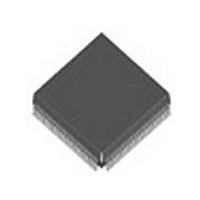
HBLXT9761HC.C4 Intel, HBLXT9761HC.C4 Datasheet - Page 20

HBLXT9761HC.C4
Manufacturer Part Number
HBLXT9761HC.C4
Description
Manufacturer
Intel
Datasheet
1.HBLXT9761HC.C4.pdf
(78 pages)
Specifications of HBLXT9761HC.C4
Lead Free Status / RoHS Status
Not Compliant
LXT9761/9781 — Fast Ethernet 10/100 Multi-Port Transceiver with RMII
20
25-30, 33-40, 98,
124-137, 162,
189-191, 194-196
1. Type Column Coding: I = Input, O = Output, A = Analog, OD = Open Drain, OS = Open Source.
2. Ports 6 and 7 are available only on the LXT9781. These pins are not bonded out on the LXT9761.
1. These pins are used for the two additional ports available on the LXT9781. They are not bonded out on the LXT9761.
PQFP
Table 7.
Table 8.
9761
Pin#
183
184
185
180
181
182
LXT9761 PQFP
–
–
–
–
–
–
Pin#
1
LXT97x1 LED Signal Descriptions (Continued)
PQFP
Unused Pins
189
190
191
186
187
188
183
184
185
180
181
182
9781
Pin#
A1,A2,B1,U1,U2,U3,U4,
U9,V9,W1,W9,
Y1,Y4,Y7
PBGA
D10
C10
A10
B10
C11
A11
C8
A8
D9
A9
B9
C9
LXT9781 PBGA
Pin#
LED/CFG4_1
LED/CFG4_2
LED/CFG4_3
LED/CFG5_1
LED/CFG5_2
LED/CFG5_3
LED/CFG6_1
LED/CFG6_2
LED/CFG6_3
LED/CFG7_1
LED/CFG7_2
LED/CFG7_3
Symbol
Symbol
I/OD/OS
I/OD/OS
I/OD/OS
I/OD/OS
Type
N/C
1
Port 4 LED Drivers 1 -3. These pins drive LED
indicators for Port 4. Each LED can display one of
several available status conditions as selected by the
LED Configuration Register (refer to
for details).
Port 4 Configuration Inputs 1-3. When operating in
Hardware Control Mode, these pins also provide
configuration control options (refer to
for details).
Port 5 LED Drivers 1 -3. These pins drive LED
indicators for Port 5. Each LED can display one of
several available status conditions as selected by the
LED Configuration Register (refer to
for details).
Port 5 Configuration Inputs 1-3. When operating in
Hardware Control Mode, these pins also provide
configuration control options (refer to
for details).
Port 6 LED Drivers 1 -3. These pins drive LED
indicators for Port 6. Each LED can display one of
several available status conditions as selected by the
LED Configuration Register (refer to
for details).
Port 6 Configuration Inputs 1-3. When operating in
Hardware Control Mode, these pins also provide
configuration control options (refer to
for details).
Port 7 LED Drivers 1 -3. These pins drive LED
indicators for Port 7. Each LED can display one of
several available status conditions as selected by the
LED Configuration Register (refer to
for details).
Port 7 Configuration Inputs 1-3. When operating in
Hardware Control Mode, these pins also provide
configuration control options (refer to
for details).
Type
–
No Connection. These pins should be left
unconnected.
Signal Description
Signal Description
Table 48 on page 74
Table 48 on page 74
Table 48 on page 74
Table 48 on page 74
Table 9 on page 29
Table 9 on page 29
Table 9 on page 29
Table 9 on page 29
2
Datasheet


