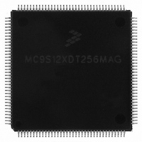
MC9S12XDT256MAG Freescale Semiconductor, MC9S12XDT256MAG Datasheet - Page 111

MC9S12XDT256MAG
Manufacturer Part Number
MC9S12XDT256MAG
Description
IC MCU 256K FLASH 144-LQFP
Manufacturer
Freescale Semiconductor
Series
HCS12r
Datasheet
1.MC9S12XD64CAA.pdf
(1348 pages)
Specifications of MC9S12XDT256MAG
Core Processor
HCS12X
Core Size
16-Bit
Speed
80MHz
Connectivity
CAN, EBI/EMI, I²C, IrDA, LIN, SCI, SPI
Peripherals
LVD, POR, PWM, WDT
Number Of I /o
119
Program Memory Size
256KB (256K x 8)
Program Memory Type
FLASH
Eeprom Size
4K x 8
Ram Size
16K x 8
Voltage - Supply (vcc/vdd)
2.35 V ~ 5.5 V
Data Converters
A/D 24x10b
Oscillator Type
External
Operating Temperature
-40°C ~ 125°C
Package / Case
144-LQFP
Processor Series
S12XD
Core
HCS12
Data Bus Width
16 bit
Data Ram Size
16 KB
Interface Type
CAN/I2C/SCI/SPI
Maximum Clock Frequency
40 MHz
Number Of Programmable I/os
119
Number Of Timers
12
Operating Supply Voltage
0 V to 5.5 V
Maximum Operating Temperature
+ 125 C
Mounting Style
SMD/SMT
3rd Party Development Tools
EWHCS12
Development Tools By Supplier
EVB9S12XDP512E
Minimum Operating Temperature
- 40 C
On-chip Adc
2 (24-ch x 10-bit)
Lead Free Status / RoHS Status
Lead free / RoHS Compliant
Available stocks
Company
Part Number
Manufacturer
Quantity
Price
Company:
Part Number:
MC9S12XDT256MAG
Manufacturer:
Freescale Semiconductor
Quantity:
10 000
- Current page: 111 of 1348
- Download datasheet (8Mb)
2.4.3.3.2
The MCU requires an external interrupt or an external reset in order to wake-up from stop-mode.
If the MCU gets an external reset during full stop mode active, the CRG asynchronously restores all
configuration bits in the register space to its default settings and will perform a maximum of 50 clock
check_windows (see
the CRG starts the reset generator. After completing the reset sequence processing begins by fetching the
normal reset vector. Full stop-mode is left and the MCU is in run mode again.
If the MCU is woken-up by an interrupt and the fast wake-up feature is disabled (FSTWKP = 0 or
SCME = 0), the CRG will also perform a maximum of 50 clock check_windows (see
“Clock Quality
core clocks and will continue with normal operation. If all clock checks within the Timeout-Window are
failing, the CRG will switch to self-clock mode or generate a clock monitor reset (CMRESET) depending
on the setting of the SCME bit.
If the MCU is woken-up by an interrupt and the fast wake-up feature is enabled (FSTWKP = 1 and
SCME = 1), the system will immediately resume operation in self-clock mode (see
Quality
oscillator disabled until FSTWKP bit is cleared. The clearing of FSTWKP will start the oscillator and the
clock quality check. If the clock quality check is successful, the CRG will switch all system clocks to
oscillator clock. The SCMIF flag will be set. See application examples in
Because the PLL has been powered-down during stop-mode the PLLSEL bit is cleared and the MCU runs
on OSCCLK after leaving stop-mode. The software must manually set the PLLSEL bit again, in order to
switch system and core clocks to the PLLCLK.
Freescale Semiconductor
Checker”). The SCMIF flag will not be set. The system will remain in self-clock mode with
Wake-up from Full Stop (PSTP = 0)
In full stop mode or self-clock mode caused by the fast wake-up feature, the
clock monitor and the oscillator are disabled.
Checker”). If the clock quality check is successful, the CRG will release all system and
Section 2.4.1.4, “Clock Quality
MC9S12XDP512 Data Sheet, Rev. 2.21
NOTE
Checker”). After completing the clock quality check
Chapter 2 Clocks and Reset Generator (S12CRGV6)
Figure 2-23
Section 2.4.1.4, “Clock
Section 2.4.1.4,
and
Figure
2-24.
111
Related parts for MC9S12XDT256MAG
Image
Part Number
Description
Manufacturer
Datasheet
Request
R

Part Number:
Description:
16-BIT MICROPROCESSOR FAMILY
Manufacturer:
FREESCALE [Freescale Semiconductor, Inc]
Datasheet:
Part Number:
Description:
Manufacturer:
Freescale Semiconductor, Inc
Datasheet:
Part Number:
Description:
Manufacturer:
Freescale Semiconductor, Inc
Datasheet:
Part Number:
Description:
Manufacturer:
Freescale Semiconductor, Inc
Datasheet:
Part Number:
Description:
Manufacturer:
Freescale Semiconductor, Inc
Datasheet:
Part Number:
Description:
Manufacturer:
Freescale Semiconductor, Inc
Datasheet:
Part Number:
Description:
Manufacturer:
Freescale Semiconductor, Inc
Datasheet:
Part Number:
Description:
Manufacturer:
Freescale Semiconductor, Inc
Datasheet:
Part Number:
Description:
Manufacturer:
Freescale Semiconductor, Inc
Datasheet:
Part Number:
Description:
Manufacturer:
Freescale Semiconductor, Inc
Datasheet:
Part Number:
Description:
Manufacturer:
Freescale Semiconductor, Inc
Datasheet:
Part Number:
Description:
Manufacturer:
Freescale Semiconductor, Inc
Datasheet:
Part Number:
Description:
Manufacturer:
Freescale Semiconductor, Inc
Datasheet:
Part Number:
Description:
Manufacturer:
Freescale Semiconductor, Inc
Datasheet:
Part Number:
Description:
Manufacturer:
Freescale Semiconductor, Inc
Datasheet:


