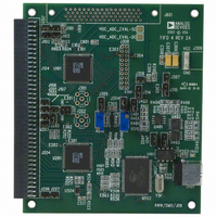
HSC-ADC-EVALA-DC Analog Devices Inc, HSC-ADC-EVALA-DC Datasheet - Page 26

HSC-ADC-EVALA-DC
Manufacturer Part Number
HSC-ADC-EVALA-DC
Description
KIT EVAL FOR DUAL ADC/CONV
Manufacturer
Analog Devices Inc
Specifications of HSC-ADC-EVALA-DC
Lead Free Status / RoHS Status
Contains lead / RoHS non-compliant
AN-905
The grid in the User-Defined tab lists computations that the
FFT Analysis component performs on the input data. Note that
the routine performs these computations in order, from top to
bottom.
Name—Sets the display name for this calculation. This display
name appears wherever the software reports the result to the
user, such as in a Graph component, Data Grid, or output to
a file. This can be any combination of letters, numbers, and
symbols. If the display name is empty, the software does not
show the result.
Symbol—The character or characters that show up on the FFT
graph display. This can be a single character or a string appro
priate for the application.
Locate—Determines how the spectral component is located.
Three methods are available for use and depend largely on the
application.
•
•
•
Freq (MHz)—The analysis uses the Freq (MHz) column when
the Locate method is set to Frequency. This text may
be a constant or a simple expression using any combination
of constants or previously defined variables. The supported
operations are addition, subtraction, division, multiplication,
and exponential. There is one system-defined constant, f
which represents the frequency sample rate.
Valid expressions include 2 * fund (assuming fund is previously
defined), 2 * f2 − f1 (assuming f1 and f2 are previously defined)
and f
addition, simple constants such as 2.3 are also valid, as is f1 −
2.3. Parentheses are also acceptable, to force the order of
operations, (2 * (f2 − f1)).
The routine will ignore this column if the Locate method is not
set to Frequency.
Frequency—Finds the spectral component by exact fre
quency in megahertz. It is important to ensure that the
sample rate is properly set or the computed frequency
may be in error. The analog frequency, if greater than the
Nyquist frequency, is automatically aliased to ensure that it
references the proper bin in the display.
Max Power—Finds the spectral component at the maxi
mum bin location in the FFT spectrum. This is most useful
for full-scale, single-tone testing where the frequency
changes often. If the signal is a modulated waveform,
this method is less reliable than Frequency.
Next Max Power—Finds the next largest signal not already
selected earlier in the list. This is useful for finding miscel
laneous spurious tones, such as a worst other spur in single-
tone analysis. When using this option, be sure to place this
item after all other items in the spectrum are to be avoided
in the next maximum computation.
S
− fund (assuming fund has been previously defined). In
S
,
Rev. 0 | Page 26 of 40
Single-Side Band–determines how many bins are included in
the given calculation. The text form can be a constant or a
simple expression. The units can be bins or megahertz,
depending on the next column setting.
Use Power As—There are six selectable actions on the
integrations defined for the analysis.
•
•
•
•
•
•
•
Power—The analysis uses the Power column when the Use
Power As method is set to the Custom option. The text format
is similar to the Freq (MHz) column in that it can be a constant
or a simple expression. This column can also use previously
defined variables. In this column, a variable represents the
power of its corresponding line item.
Variable—Variable defines local variables used in the measure
ment. These represent the component on the corresponding
line. Once defined, they are valid in all of the following
calculations. If referencing the variable in the Freq (MHz)
or Single-Side Band column, the routine uses the frequency
portion of the calculation. If referencing the variable in the
Power column, the routine uses the power portion of the
calculation.
Note that you cannot use a variable in the list before you define
it. Therefore, place all defined variables before their use.
Reference—Identifies the fundamental energy. If more than
one item is a reference, the FFT analysis combines the
energies. This can be useful when performing tests where
more than one signal may contribute to the reference
power.
Harmonic—Identifies a component whose power is meas
ured in reference to the Reference. A signal identified as a
harmonic is included in the SINAD measurement as well
as in the THD.
Spur, Exclude—Identifies spectral content that should not
be included as noise in overall calculations, but reported as
a spur. This is useful if a spurious signal from an external
source is otherwise disrupting performance. Using this
option removes the effect of the spurious signal on overall
performance.
Spur, Include—Identifies spectral content that should be
included as noise in overall calculations, but can otherwise
be of limited interest as a spur. This includes spurs such as
worst other.
Noise—Identifies spectral content that should be a band
of noise in the spectrum. This setting is useful for narrow
band noise calculations.
Remove—Identifies spectral content to remove from further
calculations. This setting also removes the frequency band
from general FFT calculations.
Custom—Identifies a custom power calculation. This
setting should be used when a power calculation is needed
that cannot be represented by the previous calculation
methods.


