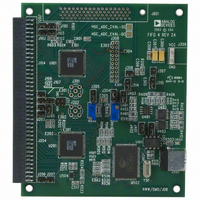
HSC-ADC-EVALA-DC Analog Devices Inc, HSC-ADC-EVALA-DC Datasheet - Page 21

HSC-ADC-EVALA-DC
Manufacturer Part Number
HSC-ADC-EVALA-DC
Description
KIT EVAL FOR DUAL ADC/CONV
Manufacturer
Analog Devices Inc
Specifications of HSC-ADC-EVALA-DC
Lead Free Status / RoHS Status
Contains lead / RoHS non-compliant
Table 3. Serialized LVDS Tuning Controls
Control
Retune
Button
LVCMOS Tuning holds the controls related to tuning for the
LVCMOS port.
Table 4. LVCMOS Tuning Controls
Control
Delay
Load
Button
Debug
The Debug tab allows you to verify functionality of the DPG.
Frequency counter allows readback of the frequency counter
from the DPG to ensure correct operation.
Table 5. Frequency Counter Controls
Control
Port Selection
Frequency
Indicator
Go Button
Description
Manual trigger to retune the clock and data bits on
the serialized LVDS port. The alignment type is based
on the selected mode (aligned or centered). Tuning
is automatically performed when playback is started.
Description
Specifies the desired delay value. The value range is
from 0 to 1023 (0x3FF) in 10 ps units. This allows a
variation of approximately 10 ns.
A manual trigger to load the specified delay value
for the clock and data bits on the LVCMOS port.
Description
Selects the output port being used before
reading back the frequency
Displays the frequency read back from the DPG
Reads back the frequency counter from the DPG
Figure 45. Debug Tab
Rev. 0 | Page 21 of 40
Tx Config
The Tx Config tab holds controls for transmission features.
Idle Pattern specifies the transmit pattern when there is no
playback in progress. A four-sample pattern can be generated.
The four-sample values in the pattern are played sequentially,
then looped and played again until a vector file playback or the
feature is disabled.
Table 6. Idle Pattern Controls
Control
Enabled
Idle
Pattern
Text
Update
Button
PATTERN LIMITATIONS
The DPG is useful for playing a large range of user vector
patterns. However, there are a few basic limitations to the data.
•
•
•
FIFO4.x INTERFACE
The FIFO4.x interface component handles all interfacing
between the ADC capture board and the software package,
simply moving data from the hardware to the software data set
(vector). This interface exists for compatibility. The preferred
ADC interface is the ADC data capture component.
Additional information is available at www.analog.com/fifo.
The sample size of the output vector must be a multiple of
16 samples.
The minimum vector length is 640 samples.
The available memory in the DMM sockets limits the
maximum vector length. Each sample takes two bytes in
memory. Complex samples count as two samples in
memory.
Description
Enables/disables the idle pattern generation
feature. When the feature is disabled, zeros are
played on the output port.
Specifies the pattern values. When operating in dual
stream mode, four patterns must be specified for
each of the two streams. The values are played
sequentially from top to bottom.
Updates the idle pattern in the DPG.
Figure 46. Tx Config Tab
AN-905


