MC56F8323EVME Freescale Semiconductor, MC56F8323EVME Datasheet - Page 11
MC56F8323EVME
Manufacturer Part Number
MC56F8323EVME
Description
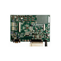
BOARD EVALUATION MC56F8323
Manufacturer
Freescale Semiconductor
Type
DSPr
Specifications of MC56F8323EVME
Contents
Module and Misc Hardware
Processor To Be Evaluated
MC56F8322 and MC56F8323
Data Bus Width
16 bit
Interface Type
RS-232
Silicon Manufacturer
Freescale
Core Architecture
56800/E
Core Sub-architecture
56800/E
Silicon Core Number
MC56F
Silicon Family Name
MC56F83xx
Rohs Compliant
Yes
For Use With/related Products
MC56F8322, MC56F8323
Lead Free Status / RoHS Status
Lead free / RoHS Compliant


Architecture Block Diagram
1.4 Architecture Block Diagram
Note: Features in italics are NOT available in the 56F8123 device and are shaded in the following figures.
The 56F8323/56F8123 architecture is shown in
Figure 1-1
and
Figure
1-2.
Figure 1-1
illustrates how the
56800E system buses communicate with internal memories and the IPBus Bridge.
Table 1-2
lists the
internal buses in the 56800E architecture and provides a brief description of their function.
Figure 1-2
shows the peripherals and control blocks connected to the IPBus Bridge. The figures do not show the
on-board regulator and power and ground signals. They also do not show the multiplexing between
peripherals or the dedicated GPIOs. Please see
Part 2 Signal/Connection
Descriptions, to see which
signals are multiplexed with those of other peripherals.
Also shown in
Figure 1-2
are connections between the PWM, Timer C and ADC blocks. These
connections allow the PWM and/or Timer C to control the timing of the start of ADC conversions. The
Timer C, Channel 2, output can generate periodic start (SYNC) signals to the ADC to start its conversions.
In another operating mode, the PWM load interrupt (SYNC output) signal is routed internally to the Timer
C, Channel 2, input as indicated. The timer can then be used to introduce a controllable delay before
generating its output signal. The timer output then triggers the ADC. To fully understand this interaction,
please see the 56F8300 Peripheral User Manual for clarification on the operation of all three of these
peripherals.
56F8323 Technical Data, Rev. 17
Freescale Semiconductor
11
Preliminary
Related parts for MC56F8323EVME
Image
Part Number
Description
Manufacturer
Datasheet
Request
R

Part Number:
Description:
Manufacturer:
Freescale Semiconductor, Inc
Datasheet:
Part Number:
Description:
Manufacturer:
Freescale Semiconductor, Inc
Datasheet:
Part Number:
Description:
Manufacturer:
Freescale Semiconductor, Inc
Datasheet:
Part Number:
Description:
Manufacturer:
Freescale Semiconductor, Inc
Datasheet:
Part Number:
Description:
Manufacturer:
Freescale Semiconductor, Inc
Datasheet:
Part Number:
Description:
Manufacturer:
Freescale Semiconductor, Inc
Datasheet:
Part Number:
Description:
Manufacturer:
Freescale Semiconductor, Inc
Datasheet:
Part Number:
Description:
Manufacturer:
Freescale Semiconductor, Inc
Datasheet:
Part Number:
Description:
Manufacturer:
Freescale Semiconductor, Inc
Datasheet:
Part Number:
Description:
Manufacturer:
Freescale Semiconductor, Inc
Datasheet:
Part Number:
Description:
Manufacturer:
Freescale Semiconductor, Inc
Datasheet:
Part Number:
Description:
Manufacturer:
Freescale Semiconductor, Inc
Datasheet:
Part Number:
Description:
Manufacturer:
Freescale Semiconductor, Inc
Datasheet:
Part Number:
Description:
Manufacturer:
Freescale Semiconductor, Inc
Datasheet:
Part Number:
Description:
Manufacturer:
Freescale Semiconductor, Inc
Datasheet: