C8051F560-TB Silicon Laboratories Inc, C8051F560-TB Datasheet - Page 211
C8051F560-TB
Manufacturer Part Number
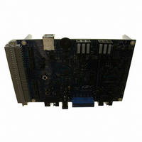
C8051F560-TB
Description
BOARD PROTOTYPE W/C8051F560
Manufacturer
Silicon Laboratories Inc
Type
MCUr
Datasheet
1.TOOLSTICK560DC.pdf
(302 pages)
Specifications of C8051F560-TB
Contents
Board
Processor To Be Evaluated
C8051F56x
Processor Series
C8051F56x
Interface Type
USB
Maximum Operating Temperature
+ 125 C
Minimum Operating Temperature
- 40 C
Operating Supply Voltage
1.8 V to 5.25 V
Lead Free Status / RoHS Status
Lead free / RoHS Compliant
For Use With/related Products
C8051F55x, C8051F56x, C8051F57x
For Use With
336-1691 - KIT DEVELOPMENT FOR C8051F560
Lead Free Status / Rohs Status
Lead free / RoHS Compliant
Other names
336-1694


The length of the 4 bit segments must be adjusted so that their sum is as close as possible to the desired
bit time. Since each segment must be an integer multiple of the time quantum (t
bit time is 24 tq (1000.008 ns), yielding a bit rate of 0.999992 Mbit/sec. The Sync_Seg is a constant 1 tq.
The Prop_Seg must be greater than or equal to the propagation delay of 400 ns and so the choice is 10 tq
(416.67 ns).
The remaining time quanta (13 tq) in the bit time are divided between Phase_Seg1 and Phase_Seg2 as
shown in. Based on this equation, Phase_Seg1 = 6 tq and Phase_Seg2 = 7 tq.
The Synchronization Jump Width (SJW) timing parameter is defined by. It is used for determining the value
written to the Bit Timing Register and for determining the required oscillator tolerance. Since we are using
a quartz crystal as the system clock source, an oscillator tolerance calculation is not needed.
The value written to the Bit Timing Register can be calculated using Equation 18.3. The BRP Extension
register is left at its reset value of 0x0000.
Bit Timing Register = (TSEG2 x 0x1000) + (TSEG1 x 0x0100) + (SJWp x 0x0040) + BRPE = 0x6FC0
1. If Phase_Seg1 + Phase_Seg2 is even, then Phase_Seg2 = Phase_Seg1. If the sum is odd, Phase_Seg2 =
2. Phase_Seg2 should be at least 2
Phase_Seg1 + 1.
1t
Phase_Seg1 + Phase_Seg2 = Bit_Time – (Synch_Seg + Prop_Seg)
Equation 21.3. Calculating the Bit Timing Register Value
q
Bit Timing Register = (TSEG2 x 0x1000) + (TSEG1 x 0x0100)
Equation 21.2. Synchronization Jump Width (SJW)
Sync_Seg
TSEG1 = Prop_Seg + Phase_Seg1 - 1 = 10 + 6 – 1 = 15
Equation 21.1. Assigning the Phase Segments
BRPE = BRP – 1 = BRP Extension Register = 0x0000
1t
Prop_Seg
Figure 21.3. Four segments of a CAN Bit
1 to 8 t
q
SJWp = SJW – 1 = minimum (4, 6) – 1 = 3
SJW = minimum (4, Phase_Seg1)
t
TSEG2 = Phase_Seg2 – 1 = 6
q
q
CAN Bit Time (4 to 25 t
.
Rev. 1.1
Phase_Seg1
1 to 8 t
q
C8051F55x/56x/57x
q
)
Phase_Seg2
Sample Point
1 to 8 t
q
), the closest achievable
q
211
Related parts for C8051F560-TB
Image
Part Number
Description
Manufacturer
Datasheet
Request
R

Part Number:
Description:
SMD/C°/SINGLE-ENDED OUTPUT SILICON OSCILLATOR
Manufacturer:
Silicon Laboratories Inc
Part Number:
Description:
Manufacturer:
Silicon Laboratories Inc
Datasheet:
Part Number:
Description:
N/A N/A/SI4010 AES KEYFOB DEMO WITH LCD RX
Manufacturer:
Silicon Laboratories Inc
Datasheet:
Part Number:
Description:
N/A N/A/SI4010 SIMPLIFIED KEY FOB DEMO WITH LED RX
Manufacturer:
Silicon Laboratories Inc
Datasheet:
Part Number:
Description:
N/A/-40 TO 85 OC/EZLINK MODULE; F930/4432 HIGH BAND (REV E/B1)
Manufacturer:
Silicon Laboratories Inc
Part Number:
Description:
EZLink Module; F930/4432 Low Band (rev e/B1)
Manufacturer:
Silicon Laboratories Inc
Part Number:
Description:
I°/4460 10 DBM RADIO TEST CARD 434 MHZ
Manufacturer:
Silicon Laboratories Inc
Part Number:
Description:
I°/4461 14 DBM RADIO TEST CARD 868 MHZ
Manufacturer:
Silicon Laboratories Inc
Part Number:
Description:
I°/4463 20 DBM RFSWITCH RADIO TEST CARD 460 MHZ
Manufacturer:
Silicon Laboratories Inc
Part Number:
Description:
I°/4463 20 DBM RADIO TEST CARD 868 MHZ
Manufacturer:
Silicon Laboratories Inc
Part Number:
Description:
I°/4463 27 DBM RADIO TEST CARD 868 MHZ
Manufacturer:
Silicon Laboratories Inc
Part Number:
Description:
I°/4463 SKYWORKS 30 DBM RADIO TEST CARD 915 MHZ
Manufacturer:
Silicon Laboratories Inc
Part Number:
Description:
N/A N/A/-40 TO 85 OC/4463 RFMD 30 DBM RADIO TEST CARD 915 MHZ
Manufacturer:
Silicon Laboratories Inc
Part Number:
Description:
I°/4463 20 DBM RADIO TEST CARD 169 MHZ
Manufacturer:
Silicon Laboratories Inc