EVAL-ADUC7128QSPZ Analog Devices Inc, EVAL-ADUC7128QSPZ Datasheet - Page 80
EVAL-ADUC7128QSPZ
Manufacturer Part Number
EVAL-ADUC7128QSPZ
Description
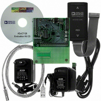
KIT DEV FOR ADUC7128
Manufacturer
Analog Devices Inc
Series
QuickStart™ PLUS Kitr
Type
MCUr
Datasheet
1.EVAL-ADUC7128QSPZ.pdf
(92 pages)
Specifications of EVAL-ADUC7128QSPZ
Contents
Evaluation Board, Power Supply, Cable, Software, Emulator and Documentation
Silicon Manufacturer
Analog Devices
Core Architecture
ARM
Core Sub-architecture
ARM7TDMI
Silicon Core Number
ADuC7128
Rohs Compliant
Yes
Lead Free Status / RoHS Status
Lead free / RoHS Compliant
For Use With/related Products
ADuC7128
Lead Free Status / RoHS Status
Lead free / RoHS Compliant, Lead free / RoHS Compliant


ADuC7128/ADuC7129
Table 115. T3CON MMR Bit Designations
Bit
16:9
8
7
6
5
4
3:2
1
0
Secure Clear Bit (Watchdog Mode Only)
The secure clear bit is provided for a higher level of protection.
When set, a specific sequential value must be written to T3ICLR
to avoid a watchdog reset. The value is a sequence generated by
the 8-bit linear feedback shift register (LFSR) polynomial equal
to X8 + X6 + X5 + X + 1, as shown in Figure 59.
CLOCK
The initial value or seed is written to T3ICLR before entering
watchdog mode. After entering watchdog mode, a write to
T3ICLR must match this expected value. If it matches, the LFSR
is advanced to the next state when the counter reload happens.
If it fails to match the expected state, reset is immediately
generated, even if the count has not yet expired.
Q
7
D
Value
00
01
10
11
Q
6
D
These bits are reserved and should be written as 0s by user code.
Timer3 Clock (32.768 kHz) Prescaler.
Reserved.
Reserved.
Reserved.
Description
Count Up/Down Enable.
Timer3 Enable.
Timer3 Operating Mode.
Watchdog Timer Mode Enable.
Secure Clear Bit.
Source Clock/1 (Default).
Watchdog Timer IRQ Enable.
PD_OFF.
Q
Set by user code to configure Timer3 to count up.
Cleared by user code to configure Timer3 to count down.
Set by user code to enable Timer3.
Cleared by user code to disable Timer3.
Set by user code to configure Timer3 to operate in periodic mode.
Cleared by user to configure Timer3 to operate in free-running mode.
Set by user code to enable watchdog mode.
Cleared by user code to disable watchdog mode.
Set by user to use the secure clear option.
Cleared by user to disable the secure clear option by default.
Set by user code to produce an IRQ instead of a reset when the watchdog reaches 0.
Cleared by user code to disable the IRQ option.
Set by user code to stop Timer3 when the peripherals are powered down via Bit 4 in the POWCON MMR.
Cleared by user code to enable Timer3 when the peripherals are powered down via Bit 4 in the POWCON MMR.
5
D
Figure 59. 8-Bit LFSR
Q
4
D
Q
3
D
Q
2
D
Q
1
D
Q
0
D
Rev. 0 | Page 80 of 92
The value 0x00 should not be used as an initial seed due to the
properties of the polynomial. The value 0x00 is always guaran-
teed to force an immediate reset. The value of the LFSR cannot
be read; it must be tracked/generated in software.
The following is an example of a sequence:
1.
2.
3.
4.
5.
Enter initial seed, 0 xAA, in T3ICLR before starting
Timer3 in watchdog mode.
Enter 0 xAA in T3ICLR; Timer3 is reloaded.
Enter 0x37 in T3ICLR; Timer3 is reloaded.
Enter 0x6E in T3ICLR; Timer3 is reloaded.
Enter 0x66. 0xDC was expected; the watchdog resets
the chip.
Related parts for EVAL-ADUC7128QSPZ
Image
Part Number
Description
Manufacturer
Datasheet
Request
R

Part Number:
Description:
IC, ADJ LDO REG, 1.5V TO 5V 250mA MSOP-8
Manufacturer:
Vishay
Datasheet:

Part Number:
Description:
IC, ADJ LDO REG, 1.5V TO 5V 0.6A 8-TSSOP
Manufacturer:
Vishay
Datasheet:
Part Number:
Description:
IC, ADJ LDO REG, 1.5V TO 5V 250mA MSOP-8
Manufacturer:
Vishay
Datasheet:

Part Number:
Description:
IC ADJ LDO REG 1.5V TO 5V 150mA 5-SOT-23
Manufacturer:
Vishay
Datasheet:

Part Number:
Description:
BOARD EVAL AS1324-AD
Manufacturer:
austriamicrosystems
Datasheet:
Part Number:
Description:
IC, ADJ LDO REG, 1.5V TO 5V 0.6A 8-TSSOP
Manufacturer:
Vishay
Datasheet:

Part Number:
Description:
IC, ADJ LDO REG, 1.5V TO 5V, 0.3A, MSOP8
Manufacturer:
Vishay
Datasheet:
Part Number:
Description:
IC, ADJ LDO REG, 1.5V TO 5V, 0.3A, MSOP8
Manufacturer:
Vishay
Datasheet:
Part Number:
Description:
IC, ADJ LDO REG 1.215V TO 5V 0.3A MSOP-8
Manufacturer:
Vishay
Datasheet:
Part Number:
Description:
IC, ADJ LDO REG 1.215V TO 5V 0.3A MSOP-8
Manufacturer:
Vishay
Datasheet:

Part Number:
Description:
±1.7g Dual-Axis IMEMS Accelerometer Evaluation Board
Manufacturer:
Analog Devices Inc
Datasheet:

Part Number:
Description:
IC MULTIPLIER ANALOG 8-SOIC T/R
Manufacturer:
Analog Devices Inc
Datasheet:

Part Number:
Description:
IC ANALOG MULTIPLIER 8-DIP
Manufacturer:
Analog Devices Inc
Datasheet:
Part Number:
Description:
IC ANALOG MULTIPLIER 8-SOIC
Manufacturer:
Analog Devices Inc
Datasheet:
Part Number:
Description:
IC ANALOG MULTIPLIER 8-DIP
Manufacturer:
Analog Devices Inc
Datasheet: