EVAL-ADUC847QSZ Analog Devices Inc, EVAL-ADUC847QSZ Datasheet - Page 63
EVAL-ADUC847QSZ
Manufacturer Part Number
EVAL-ADUC847QSZ
Description
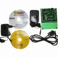
KIT DEV QUICK START FOR ADUC847
Manufacturer
Analog Devices Inc
Series
QuickStart™ Kitr
Type
MCUr
Datasheet
1.EVAL-ADUC845QSZ.pdf
(108 pages)
Specifications of EVAL-ADUC847QSZ
Contents
Evaluation Board, Power Supply, Cable, Software and Documentation
Silicon Manufacturer
Analog Devices
Core Architecture
8051
Silicon Core Number
ADuC847
Tool / Board Applications
General Purpose MCU, MPU, DSP, DSC
Mcu Supported Families
ADUC8xx
Development Tool Type
Hardware - Eval/Demo Board
Rohs Compliant
Yes
Lead Free Status / RoHS Status
Lead free / RoHS Compliant
For Use With/related Products
ADuC847
Lead Free Status / RoHS Status
Lead free / RoHS Compliant, Lead free / RoHS Compliant


Hardware Slave Mode
After reset, the ADuC845/ADuC847/ADuC848 default to
hardware slave mode. The I
the SPE bit in SPICON. Slave mode is enabled by clearing the
I2CM bit in I2CCON. The parts have a full hardware slave. In
slave mode, the I
Data received or to be transmitted is stored in the I2CDAT
register.
Once enabled in I
a start condition. If the parts detect a valid start condition,
followed by a valid address, followed by the R/W bit, then the
I2CI interrupt bit is automatically set by hardware. The I
peripheral generates a core interrupt only if the user has pre-
configured the I
as the global interrupt bit, EA, in the IE SFR. Therefore,
MOV IEIP2, #01h
SETB EA
An autoclear of the I2CI bit is implemented on the parts so that
this bit is cleared automatically upon read or write access to the
I2CDAT SFR.
MOV I2CDAT, A
MOV A, I2CDAT
If for any reason the user tries to clear the interrupt more than
once, that is, access the data SFR more than once per interrupt,
the I
using the I2CRS bit.
The user can choose to poll the I2CI bit or to enable the
interrupt. In the case of the interrupt, the PC counter vectors to
003BH at the end of each complete byte. For the first byte, when
the user gets to the I2CI ISR, the 7-bit address and the R/W bit
appear in the I2CDAT SFR.
2
C controller stops. The interface then must be reset by
2
2
C interrupt enable bit in the IEIP2 SFR as well
C address is stored in the I2CADD register.
2
C slave mode, the slave controller waits for
2
C interface is enabled by clearing
;Enable I
;I2CI auto-cleared
;I2CI auto-cleared
2
C Interrupt
2
C
Rev. B | Page 63 of 108
The I2CTX bit contains the R/W bit sent from the master. If
I2CTX is set, the master is ready to receive a byte; therefore the
slave transmits data by writing to the I2CDAT register. If I2CTX
is cleared, the master is ready to transmit a byte; therefore the
slave receives a serial byte. Software can interrogate the state of
I2CTX to determine whether it should write to or read from
I2CDAT.
Once the part has received a valid address, hardware holds
SCLOCK low until the I2CI bit is cleared by software. This
allows the master to wait for the slave to be ready before
transmitting the clocks for the next byte.
The I2CI interrupt bit is set every time a complete data byte is
received or transmitted, provided that it is followed by a valid
ACK. If the byte is followed by a NACK, an interrupt is not
generated.
The part continues to issue interrupts for each complete data
byte transferred until a stop condition is received or the interface
is reset.
When a stop condition is received, the interface resets to a state
in which it is waiting to be addressed (idle). Similarly, if the
interface receives a NACK at the end of a sequence, it also
returns to the default idle state. The I2CRS bit can be used to
reset the I
back to the default idle state.
2
C interface. This bit can be used to force the interface
ADuC845/ADuC847/ADuC848
Related parts for EVAL-ADUC847QSZ
Image
Part Number
Description
Manufacturer
Datasheet
Request
R


Part Number:
Description:
BOARD EVAL FOR SI270X-A
Manufacturer:
Silicon Laboratories Inc
Datasheet:

Part Number:
Description:
BUCK CONV REF DESIGN KIT IP1201
Manufacturer:
International Rectifier
Datasheet:
Part Number:
Description:
BOARD DEMO SYNC DUAL BUCK CNVTER
Manufacturer:
International Rectifier
Datasheet:
Part Number:
Description:
BOARD DEMO SYNC BUCK CONVETER
Manufacturer:
International Rectifier
Datasheet:

Part Number:
Description:
EVALBOARD/EB Omnidirectional microphone - Analog
Manufacturer:
Analog Devices
Datasheet:
Part Number:
Description:
EVALBOARD/EB Omnidirectional microphone - Analog
Manufacturer:
Analog Devices
Datasheet:


Part Number:
Description:
BOARD EVAL LED DRIVER LT3756
Manufacturer:
Linear Technology
Datasheet:

Part Number:
Description:
BOARD EVAL FOR AD7741/7742
Manufacturer:
Analog Devices Inc
Datasheet:

Part Number:
Description:
±1.7g Dual-Axis IMEMS Accelerometer Evaluation Board
Manufacturer:
Analog Devices Inc
Datasheet:

Part Number:
Description:
IC MULTIPLIER ANALOG 8-SOIC T/R
Manufacturer:
Analog Devices Inc
Datasheet:

Part Number:
Description:
IC ANALOG MULTIPLIER 8-DIP
Manufacturer:
Analog Devices Inc
Datasheet:
Part Number:
Description:
IC ANALOG MULTIPLIER 8-SOIC
Manufacturer:
Analog Devices Inc
Datasheet:
Part Number:
Description:
IC ANALOG MULTIPLIER 8-DIP
Manufacturer:
Analog Devices Inc
Datasheet: