C8051F120DK Silicon Laboratories Inc, C8051F120DK Datasheet - Page 127
C8051F120DK
Manufacturer Part Number
C8051F120DK
Description
DEVKIT-F120/21/22/23/24/25/26/27
Manufacturer
Silicon Laboratories Inc
Type
MCUr
Datasheet
1.C8051F120DK.pdf
(350 pages)
Specifications of C8051F120DK
Contents
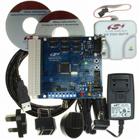
Evaluation Board, Power Supply, USB Cables, Adapter and Documentation
Processor To Be Evaluated
C8051F12x and C8051F13x
Interface Type
USB
Silicon Manufacturer
Silicon Labs
Core Architecture
8051
Silicon Core Number
C8051F120
Silicon Family Name
C8051F12x
Lead Free Status / RoHS Status
Contains lead / RoHS non-compliant
For Use With/related Products
C8051F120, 121, 122, 123, 124, 125, 126, 127
Lead Free Status / Rohs Status
Lead free / RoHS Compliant
Other names
336-1224
Available stocks
Company
Part Number
Manufacturer
Quantity
Price
Company:

Part Number:
C8051F120DK
Manufacturer:
SiliconL
Quantity:
4


11. CIP-51 Microcontroller
The MCU system controller core is the CIP-51 microcontroller. The CIP-51 is fully compatible with the
MCS-51™ instruction set; standard 803x/805x assemblers and compilers can be used to develop soft-
ware. The MCU family has a superset of all the peripherals included with a standard 8051. Included are
five 16-bit counter/timers (see description in
tion 21
space (see
includes on-chip debug hardware (see description in
analog and digital subsystems providing a complete data acquisition or control-system solution in a single
integrated circuit.
The CIP-51 Microcontroller core implements the standard 8051 organization and peripherals as well as
additional custom peripherals and functions to extend its capability (see Figure 11.1 for a block diagram).
-
-
-
-
The CIP-51 includes the following features:
Performance
The CIP-51 employs a pipelined architecture that greatly increases its instruction throughput over the stan-
dard 8051 architecture. In a standard 8051, all instructions except for MUL and DIV take 12 or 24 system
clock cycles to execute, and usually have a maximum system clock of 12 MHz. By contrast, the CIP-51
core executes 70% of its instructions in one or two system clock cycles, with no instructions taking more
than eight system clock cycles.
With the CIP-51's system clock running at 100 MHz, it has a peak throughput of 100 MIPS. The CIP-51
has a total of 109 instructions. The table below shows the total number of instructions that require each
execution time.
Number of Instructions
Fully Compatible with MCS-51 Instruction Set
100 or 50 MIPS Peak Using the On-Chip PLL
256 Bytes of Internal RAM
8/4 Byte-Wide I/O Ports
Clocks to Execute
and
Section 11.2.6
Section 22
), 256 bytes of internal RAM, 128 byte Special Function Register (SFR) address
), and 8/4 byte-wide I/O Ports (see description in
26
1
50
2
Section 23
2/3
Rev. 1.4
5
Section 25
-
-
-
-
-
C8051F120/1/2/3/4/5/6/7
), two full-duplex UARTs (see description in
14
3
Extended Interrupt Handler
Reset Input
Power Management Modes
On-chip Debug Logic
Program and Data Memory Security
), and interfaces directly with the MCU’s
3/4
7
C8051F130/1/2/3
4
3
Section 18
4/5
1
). The CIP-51 also
5
2
8
1
Sec-
127
Related parts for C8051F120DK
Image
Part Number
Description
Manufacturer
Datasheet
Request
R

Part Number:
Description:
SMD/C°/SINGLE-ENDED OUTPUT SILICON OSCILLATOR
Manufacturer:
Silicon Laboratories Inc
Part Number:
Description:
Manufacturer:
Silicon Laboratories Inc
Datasheet:
Part Number:
Description:
N/A N/A/SI4010 AES KEYFOB DEMO WITH LCD RX
Manufacturer:
Silicon Laboratories Inc
Datasheet:
Part Number:
Description:
N/A N/A/SI4010 SIMPLIFIED KEY FOB DEMO WITH LED RX
Manufacturer:
Silicon Laboratories Inc
Datasheet:
Part Number:
Description:
N/A/-40 TO 85 OC/EZLINK MODULE; F930/4432 HIGH BAND (REV E/B1)
Manufacturer:
Silicon Laboratories Inc
Part Number:
Description:
EZLink Module; F930/4432 Low Band (rev e/B1)
Manufacturer:
Silicon Laboratories Inc
Part Number:
Description:
I°/4460 10 DBM RADIO TEST CARD 434 MHZ
Manufacturer:
Silicon Laboratories Inc
Part Number:
Description:
I°/4461 14 DBM RADIO TEST CARD 868 MHZ
Manufacturer:
Silicon Laboratories Inc
Part Number:
Description:
I°/4463 20 DBM RFSWITCH RADIO TEST CARD 460 MHZ
Manufacturer:
Silicon Laboratories Inc
Part Number:
Description:
I°/4463 20 DBM RADIO TEST CARD 868 MHZ
Manufacturer:
Silicon Laboratories Inc
Part Number:
Description:
I°/4463 27 DBM RADIO TEST CARD 868 MHZ
Manufacturer:
Silicon Laboratories Inc
Part Number:
Description:
I°/4463 SKYWORKS 30 DBM RADIO TEST CARD 915 MHZ
Manufacturer:
Silicon Laboratories Inc
Part Number:
Description:
N/A N/A/-40 TO 85 OC/4463 RFMD 30 DBM RADIO TEST CARD 915 MHZ
Manufacturer:
Silicon Laboratories Inc
Part Number:
Description:
I°/4463 20 DBM RADIO TEST CARD 169 MHZ
Manufacturer:
Silicon Laboratories Inc