LP5526TLEV National Semiconductor, LP5526TLEV Datasheet - Page 6
LP5526TLEV
Manufacturer Part Number
LP5526TLEV
Description
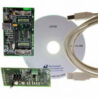
BOARD EVAL LP5526 LMU LED DRIVER
Manufacturer
National Semiconductor
Series
PowerWise®r
Specifications of LP5526TLEV
Current - Output / Channel
150mA
Outputs And Type
2 (25mA), 1 (150mA)
Voltage - Output
20 V
Features
Camera Flash, Dimmable, RGB Controller
Voltage - Input
3 ~ 5.5V
Utilized Ic / Part
LP5526
Lead Free Status / RoHS Status
Not applicable / Not applicable


www.national.com
Modes of Operation
RESET:
STANDBY:
STARTUP:
BOOST STARTUP: Soft start for boost output is generated in the BOOST STARTUP mode. The boost output is raised in low
NORMAL:
In the RESET mode all the internal registers are reset to the default values. Reset is entered always if input
NRST is LOW or internal Power On Reset is active. Power On Reset (POR) will activate during the chip
startup or when the supply voltages V
POR will inactivate and the chip will continue to the STANDBY mode. NSTBY control bit is low after POR by
default.
The STANDBY mode is entered if the register bit NSTBY is LOW and Reset is not active. This is the low
power consumption mode, when all circuit functions are disabled. Registers can be written in this mode and
the control bits are effective immediately after start up.
When NSTBY bit is written high, the INTERNAL STARTUP SEQUENCE powers up all the needed internal
blocks (V
by the internal state-machine. If the chip temperature rises too high, the Thermal Shutdown (TSD) disables
the chip operation and STARTUP mode is entered until no thermal shutdown event is present.
current PWM mode during the 20ms delay generated by the state-machine. All LED outputs are off during
the 20ms delay to ensure smooth startup. The Boost startup is entered from Internal Startup Sequence if
EN_BOOST is HIGH or from Normal mode when EN_BOOST is written HIGH.
During NORMAL mode the user controls the chip using the Control Registers. The registers can be written
in any sequence and any number of bits can be altered in a register in one write.
REF
, Bias, Oscillator etc.). To ensure the correct oscillator initialization, a 10ms delay is generated
DD1
and V
6
DD2
fall below 1.5V. Once V
20179775
DD1
and V
DD2
rises above 1.5V,
Related parts for LP5526TLEV
Image
Part Number
Description
Manufacturer
Datasheet
Request
R

Part Number:
Description:
National Semiconductor [8-Bit D/A Converter]
Manufacturer:
National Semiconductor
Datasheet:
Part Number:
Description:
National Semiconductor [Media Coprocessor]
Manufacturer:
National Semiconductor
Datasheet:
Part Number:
Description:
Digitally Controlled Tone and Volume Circuit with Stereo Audio Power Amplifier, Microphone Preamp Stage and National 3D Sound
Manufacturer:
National Semiconductor
Datasheet:
Part Number:
Description:
Digitally Controlled Tone and Volume Circuit with Stereo Audio Power Amplifier, Microphone Preamp Stage and National 3D Sound
Manufacturer:
National Semiconductor
Datasheet:
Part Number:
Description:
AC97 Rev 2 Codec with Sample Rate Conversion and National 3D Sound
Manufacturer:
National Semiconductor
Part Number:
Description:
Manufacturer:
National Semiconductor
Datasheet:
Part Number:
Description:
Manufacturer:
National Semiconductor
Datasheet:
Part Number:
Description:
General Purpose, Low Voltage, Low Power, Rail-to-Rail Output Operational Amplifiers
Manufacturer:
National Semiconductor
Datasheet:
Part Number:
Description:
8-bit 20 MSPS flash A/D converter.
Manufacturer:
National Semiconductor
Datasheet:
Part Number:
Description:
Low Noise Quad Operational Amplifier
Manufacturer:
National Semiconductor
Datasheet:
Part Number:
Description:
Quad Differential Line Receivers
Manufacturer:
National Semiconductor
Datasheet:
Part Number:
Description:
Quad High Speed Trapezoidal? Bus Transceiver
Manufacturer:
National Semiconductor
Datasheet:
Part Number:
Description:
Dual Line Receiver
Manufacturer:
National Semiconductor
Datasheet:
Part Number:
Description:
TTL to 10k ECL Level Translator with Latch
Manufacturer:
National Semiconductor
Datasheet: