LP5526TLEV National Semiconductor, LP5526TLEV Datasheet - Page 17
LP5526TLEV
Manufacturer Part Number
LP5526TLEV
Description
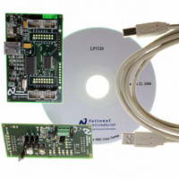
BOARD EVAL LP5526 LMU LED DRIVER
Manufacturer
National Semiconductor
Series
PowerWise®r
Specifications of LP5526TLEV
Current - Output / Channel
150mA
Outputs And Type
2 (25mA), 1 (150mA)
Voltage - Output
20 V
Features
Camera Flash, Dimmable, RGB Controller
Voltage - Input
3 ~ 5.5V
Utilized Ic / Part
LP5526
Lead Free Status / RoHS Status
Not applicable / Not applicable


Symbol
I
I
R
ƒ
V
LEAKAGE
MAX(RGB)
RGB
SAT
SW
FLASH SAFETY TIMER FUNCTION
Flash safety function can be used to prevent damages due to
possible overheating when flash or RGB LEDs have been
stuck on because of software or user error. Safety function
has two operation modes:
1.
2.
Flash safety function can be individually enabled for all RGB
LED
EN_SAFETY_B). The safety function operation mode de-
pends on the state of EN_FLASH bit.
1.
RGB LEDs Driver Performance Characteristics
Note: RGB current should be limited as follows:
constant current mode – limited by external R
switch mode – limited by external ballast resistors
Disabling selected RGB drivers when no writing has
been done to the RGB max current register (address
02H) for 1 second
Disabling selected RGB drivers if the external flash
trigger pulse is longer than 1 second
EN_FLASH = 0: Safety counter starts counting when at
least one of the EN_SAFETY_X bits is enabled. Safety
counter can be cleared by executing an I
drivers
Output Current vs Pin Voltage (CC Mode)
Parameter
RLED, GLED, BLED pin leakage current
Maximum recommended sink current
Accuracy @ 50mA
Current mirror ratio
RGB current matching error
Switch resistance
RGB internal PWM switching frequency Accuracy same as internal clock frequency
Saturation voltage (current drop 10%)
(EN_SAFETY_R,
RGB
resistor
EN_SAFETY_G,
2
C read or write
20179705
Condition
CC mode
SW mode
CC mode
CC mode
I
SW mode
accuracy
+25ºC, I
-30ºC
+85ºC
RGB
set to 50mA, CC mode
RGB
17
set to 50mA
2.
In both cases (EN_FLASH = 0/1) after one second is reached
and the LEDs which safety bit has been enabled are switched
off, the LED state can be restored by disabling the safety
function of the corresponding LED. Counter can be cleared
only by disabling all safety bits (EN_SAFETY_R = 0,
EN_SAFETY_G = 0, EN_SAFETY_B = 0), I
sequence to address 02H does not clear the counter when
safety function has been activated.
sequence to address 02H. If safety counter reaches one
second, the LEDs which have the safety function
enabled, are switched off. Also the read-only bit
SAFETY_SET is set high.
EN_FLASH = 1: Safety counter starts counting when the
external flash trigger pulse starts (GPIO[0]/PWM goes
high) and stops counting when flash pulse stops (GPIO
[0]/PWM goes low). If flash pulse is longer than one
second, the LEDs which have the safety function
enabled, are switched off. Also the read-only bit
SAFETY_SET is set high.
Output Current vs R
RGB
Min
(CC Mode)
Typ
1:100
230
3.2
20
5
2
2
C read or write
20179706
www.national.com
Max Units
12.5
350
300
430
50
60
1
kHz
mA
mA
mV
µA
%
%
Ω
Related parts for LP5526TLEV
Image
Part Number
Description
Manufacturer
Datasheet
Request
R

Part Number:
Description:
National Semiconductor [8-Bit D/A Converter]
Manufacturer:
National Semiconductor
Datasheet:
Part Number:
Description:
National Semiconductor [Media Coprocessor]
Manufacturer:
National Semiconductor
Datasheet:
Part Number:
Description:
Digitally Controlled Tone and Volume Circuit with Stereo Audio Power Amplifier, Microphone Preamp Stage and National 3D Sound
Manufacturer:
National Semiconductor
Datasheet:
Part Number:
Description:
Digitally Controlled Tone and Volume Circuit with Stereo Audio Power Amplifier, Microphone Preamp Stage and National 3D Sound
Manufacturer:
National Semiconductor
Datasheet:
Part Number:
Description:
AC97 Rev 2 Codec with Sample Rate Conversion and National 3D Sound
Manufacturer:
National Semiconductor
Part Number:
Description:
Manufacturer:
National Semiconductor
Datasheet:
Part Number:
Description:
Manufacturer:
National Semiconductor
Datasheet:
Part Number:
Description:
General Purpose, Low Voltage, Low Power, Rail-to-Rail Output Operational Amplifiers
Manufacturer:
National Semiconductor
Datasheet:
Part Number:
Description:
8-bit 20 MSPS flash A/D converter.
Manufacturer:
National Semiconductor
Datasheet:
Part Number:
Description:
Low Noise Quad Operational Amplifier
Manufacturer:
National Semiconductor
Datasheet:
Part Number:
Description:
Quad Differential Line Receivers
Manufacturer:
National Semiconductor
Datasheet:
Part Number:
Description:
Quad High Speed Trapezoidal? Bus Transceiver
Manufacturer:
National Semiconductor
Datasheet:
Part Number:
Description:
Dual Line Receiver
Manufacturer:
National Semiconductor
Datasheet:
Part Number:
Description:
TTL to 10k ECL Level Translator with Latch
Manufacturer:
National Semiconductor
Datasheet: