LP5526TLEV National Semiconductor, LP5526TLEV Datasheet - Page 14
LP5526TLEV
Manufacturer Part Number
LP5526TLEV
Description
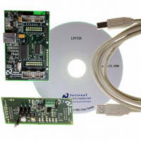
BOARD EVAL LP5526 LMU LED DRIVER
Manufacturer
National Semiconductor
Series
PowerWise®r
Specifications of LP5526TLEV
Current - Output / Channel
150mA
Outputs And Type
2 (25mA), 1 (150mA)
Voltage - Output
20 V
Features
Camera Flash, Dimmable, RGB Controller
Voltage - Input
3 ~ 5.5V
Utilized Ic / Part
LP5526
Lead Free Status / RoHS Status
Not applicable / Not applicable


www.national.com
FLASH LED DRIVING USING RGB DRIVERS
RGB drivers can be connected in parallel and used as a flash
LED driver (see Typical application 2). Flash LEDs can be
powered through the boost converter. Flash LEDs are con-
trolled basically the same way as RGB LEDs controlling is
previously described. Additional safety mode is introduced for
FLASH LED driving to avoid prolonged flash and damage to
application. FLASH can be done in 3 different ways:
1.
2.
3.
1. Using External PWM control
In this case pre-flash brightness is adjusted by adjusting the
pulse width of PWM signal
•
2. Controlling RGB Max Current Register Values
In this case pre-flash brightness is adjusted by adjusting the
current values in the RGB max current register. Note that in
this mode flash control speed and timing depends on the I
communication speed.
•
•
•
Enable external PWM pin by writing EN_PWM_PIN bit
high
Enable RGB functions and disable PWM mode (EN_RGB
= 1, RGB_PWM = 0)
Enable RGB constant current mode (CC_SW = 0)
Write pre-flash values for each output to RGB max current
register (e.g. 00b for 25% of maximum current)
Using external PWM control
Controlling RGB max current register values
Using Flash mode
Using External PWM Control for Flash
2
C
14
•
•
•
•
•
•
•
•
•
Use EN_EXT_R_PWM, EN_EXT_G_PWM and
EN_EXT_B_PWM bits to select, which LED outputs are
controlled by the external PWM control. Output which
external PWM control is not selected will be on constantly
regardless of the state of the external PWM pin.
Enable RGB constant current mode, if external ballast
resistors are not used (CC_SW = 0)
Disable internal RGB PWM mode (RGB_PWM = 0)
Write wanted maximum current values for each output to
RGB max current register (e.g. 11b for maximum current)
Enable RGB functions (EN_RGB = 1, RSW= 1, GSW= 1,
BSW = 1)
Use external PWM control pin (GPIO[0]/PWM) to
introduce pre-flash and flash.
Start pre-flash by switching on the LEDs (RSW = 1, GSW
= 1, BSW = 1). Pre-flash brightness can be adjusted also
by setting on only one or two LEDs during the pre-flash
Start flash by writing each output maximum current values
to RGB max current register
Stop flash by switching off the LEDs (RSW = 0, GSW = 0,
BSW = 0)
20179702
Related parts for LP5526TLEV
Image
Part Number
Description
Manufacturer
Datasheet
Request
R

Part Number:
Description:
National Semiconductor [8-Bit D/A Converter]
Manufacturer:
National Semiconductor
Datasheet:
Part Number:
Description:
National Semiconductor [Media Coprocessor]
Manufacturer:
National Semiconductor
Datasheet:
Part Number:
Description:
Digitally Controlled Tone and Volume Circuit with Stereo Audio Power Amplifier, Microphone Preamp Stage and National 3D Sound
Manufacturer:
National Semiconductor
Datasheet:
Part Number:
Description:
Digitally Controlled Tone and Volume Circuit with Stereo Audio Power Amplifier, Microphone Preamp Stage and National 3D Sound
Manufacturer:
National Semiconductor
Datasheet:
Part Number:
Description:
AC97 Rev 2 Codec with Sample Rate Conversion and National 3D Sound
Manufacturer:
National Semiconductor
Part Number:
Description:
Manufacturer:
National Semiconductor
Datasheet:
Part Number:
Description:
Manufacturer:
National Semiconductor
Datasheet:
Part Number:
Description:
General Purpose, Low Voltage, Low Power, Rail-to-Rail Output Operational Amplifiers
Manufacturer:
National Semiconductor
Datasheet:
Part Number:
Description:
8-bit 20 MSPS flash A/D converter.
Manufacturer:
National Semiconductor
Datasheet:
Part Number:
Description:
Low Noise Quad Operational Amplifier
Manufacturer:
National Semiconductor
Datasheet:
Part Number:
Description:
Quad Differential Line Receivers
Manufacturer:
National Semiconductor
Datasheet:
Part Number:
Description:
Quad High Speed Trapezoidal? Bus Transceiver
Manufacturer:
National Semiconductor
Datasheet:
Part Number:
Description:
Dual Line Receiver
Manufacturer:
National Semiconductor
Datasheet:
Part Number:
Description:
TTL to 10k ECL Level Translator with Latch
Manufacturer:
National Semiconductor
Datasheet: