LP5526TLEV National Semiconductor, LP5526TLEV Datasheet - Page 11
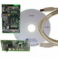
LP5526TLEV
Manufacturer Part Number
LP5526TLEV
Description
BOARD EVAL LP5526 LMU LED DRIVER
Manufacturer
National Semiconductor
Series
PowerWise®r
Specifications of LP5526TLEV
Current - Output / Channel
150mA
Outputs And Type
2 (25mA), 1 (150mA)
Voltage - Output
20 V
Features
Camera Flash, Dimmable, RGB Controller
Voltage - Input
3 ~ 5.5V
Utilized Ic / Part
LP5526
Lead Free Status / RoHS Status
Not applicable / Not applicable


Functionality of Color LED Outputs
(RLED, GLED, BLED)
LP5526 has one RGB/color LED output, consisting of three
individual LED output pins. Output pins can be used in switch
mode or constant current mode. Output mode can be selected
with the control register (address 00H) bit CC_SW. If the bit
is set high, then RGB outputs are in switch mode, otherwise
in constant current mode. These modes are described later
in separate chapters.
RGB LED output control can be done in three ways:
1.
2.
3.
1. BRIGHTNESS CONTROL WITH RGB REGISTER
If the RGB LED output is used by defining the balance and
brightness in the RGB register, then one needs to set
EN_RGB bit high and RGB_PWM bit high in the Control reg-
ister (address 00H). RSW, GSW and BSW are used to enable
each LED output, enabled when written high. CC_SW defines
the LED output mode. A single register is used for defining
the color and brightness for the RGB LED output. OVL bit
selects overlapping/non-overlapping mode. Overlapping
mode is selected when OVL = 1.
16 colors can be selected as follows. Please note that exact color depends on RGB LED current and type. Color setting is valid
only in non-overlapping mode.
Defining the expected color and brightness with internal
PWM in RGB register (address 01H)
Direct setting each LED ON/OFF via RGB Control
register (address 00H)
External PWM control
COLOR[3:0]
0000
0001
0010
0011
0100
0101
0110
0111
1000
1001
1010
1011
1100
1101
1110
1111
active [%]
RED
100
50
50
33
50
25
25
25
75
25
25
0
0
0
0
0
active [%]
GREEN
100
50
50
33
25
50
50
25
25
75
75
25
11
0
0
0
0
Brightness control is logarithmic and is programmed as fol-
lows:
BRIGHT[2:0]
Bright[2:0] Brightness [%]
COLOR[3:0]
RGB_PWM
EN_RGB
CC_SW
Name
RSW
GSW
BSW
000
001
010
011
100
101
110
111
OVL
CONTROL REGISTER (00H)
active [%]
7:4
3:1
Bit
7
6
5
3
2
1
0
RGB REGISTER (01H)
BLUE
100
1.56
3.12
6.25
12.5
50
50
33
25
25
25
50
25
75
75
100
0
0
0
0
0
25
50
0
Description
0 = Internal PWM control disabled
1 = Internal PWM control enabled
0 = RGB outputs disabled
1 = RGB outputs enabled
0 = Constant current sink mode
1 = Switch mode
0 = RLED disabled
1 = RLED enabled
0 = GLED disabled
1 = GLED enabled
0 = BLED disabled
1 = BLED enabled
Color for RGB LED output
Brightness control
0 = Non-overlapping mode
1 = Overlapping mode
Ratio to max brightness
RGB COLOR
spring green
lawn green
light green
deep pink
magenta
light blue
sky blue
1/64
1/32
1/16
orange
yellow
1/8
1/4
1/2
1/1
indigo
green
white
cyan
0
blue
pink
red
www.national.com
Related parts for LP5526TLEV
Image
Part Number
Description
Manufacturer
Datasheet
Request
R

Part Number:
Description:
National Semiconductor [8-Bit D/A Converter]
Manufacturer:
National Semiconductor
Datasheet:
Part Number:
Description:
National Semiconductor [Media Coprocessor]
Manufacturer:
National Semiconductor
Datasheet:
Part Number:
Description:
Digitally Controlled Tone and Volume Circuit with Stereo Audio Power Amplifier, Microphone Preamp Stage and National 3D Sound
Manufacturer:
National Semiconductor
Datasheet:
Part Number:
Description:
Digitally Controlled Tone and Volume Circuit with Stereo Audio Power Amplifier, Microphone Preamp Stage and National 3D Sound
Manufacturer:
National Semiconductor
Datasheet:
Part Number:
Description:
AC97 Rev 2 Codec with Sample Rate Conversion and National 3D Sound
Manufacturer:
National Semiconductor
Part Number:
Description:
Manufacturer:
National Semiconductor
Datasheet:
Part Number:
Description:
Manufacturer:
National Semiconductor
Datasheet:
Part Number:
Description:
General Purpose, Low Voltage, Low Power, Rail-to-Rail Output Operational Amplifiers
Manufacturer:
National Semiconductor
Datasheet:
Part Number:
Description:
8-bit 20 MSPS flash A/D converter.
Manufacturer:
National Semiconductor
Datasheet:
Part Number:
Description:
Low Noise Quad Operational Amplifier
Manufacturer:
National Semiconductor
Datasheet:
Part Number:
Description:
Quad Differential Line Receivers
Manufacturer:
National Semiconductor
Datasheet:
Part Number:
Description:
Quad High Speed Trapezoidal? Bus Transceiver
Manufacturer:
National Semiconductor
Datasheet:
Part Number:
Description:
Dual Line Receiver
Manufacturer:
National Semiconductor
Datasheet:
Part Number:
Description:
TTL to 10k ECL Level Translator with Latch
Manufacturer:
National Semiconductor
Datasheet: