NCP1605FORWGEVB ON Semiconductor, NCP1605FORWGEVB Datasheet - Page 18
NCP1605FORWGEVB
Manufacturer Part Number
NCP1605FORWGEVB
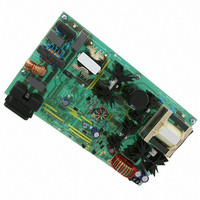
Description
EVAL BOARD FOR NCP1605FORWG
Manufacturer
ON Semiconductor
Datasheets
1.NCP1217P100G.pdf
(19 pages)
2.NCP1605ADR2G.pdf
(32 pages)
3.NCP1605FORWGEVB.pdf
(2 pages)
4.NCP1605FORWGEVB.pdf
(20 pages)
Specifications of NCP1605FORWGEVB
Design Resources
NCP1605FORWGEVB BOM NCP1605FORWGEVB Gerber Files NCP1605 EVB Schematic
Main Purpose
AC/DC, Primary and Secondary Side with PFC
Outputs And Type
1, Isolated
Voltage - Output
19V
Current - Output
8A
Voltage - Input
90 ~ 265VAC
Regulator Topology
Forward Converter
Frequency - Switching
133kHz
Board Type
Fully Populated
Utilized Ic / Part
NCP1217, NCP1605
Lead Free Status / RoHS Status
Lead free / RoHS Compliant
Power - Output
-
Lead Free Status / Rohs Status
Lead free / RoHS Compliant
For Use With/related Products
NCP1605FORWG
Other names
NCP1605FORWGEVBOS


NCP1605(A) Operation Modes
•
•
•
NCP1605 On−time Modulation
The initial inductor current of each switching cycle is
always zero. The coil current ramps up when the MOSFET
is on. The slope is (V
At the end of the on−time (t1), the coil demagnetization
phase starts. The coil current ramps down until this
sequence ends when it reaches zero. The duration of this
phase is (t2). The system enters then the dead−time (t3) that
lasts until the next clock is generated.
Like the NCP1601, the NCP1605(A):
Let’s study the ac line current absorbed by the PFC boost.
Features a current sense block that prevents the PFC
stage from operating in CCM: as long as the coil
current is not null, the power switch is not allowed to
turn on. Hence the circuit can only operate in either
Fixed Frequency DCM or CRM.
Features the capability to exhibit near−unity power
factor while operating in any type of Discontinuous
Conduction Mode operation: DCM or CRM.
Auto adapts: if there is some current flowing through
the coil when the clock occurs to initiate a new current
cycle, the PFC stage enters CRM. On the other hand,
if the clock occurs during dead−times, one obtains a
fixed frequency operation DCM. Thanks to its special
oscillator/synchronization arrangement, the circuit
automatically enters the appropriate mode CRM or
IN
Current
/L) where L is the coil inductance.
The NCP1605(A) can jump from DCM to CRM within a sinusoid cycle (and vice versa)
DCM
Figure 52. DCM and CRM Operation Within a Sinusoid Cycle
without any discontinuity in the current shaping or the power transfer.
Critical Mode
http://onsemi.com
18
inductor current compared to CRM for the same delivered
power. Hence, the coil is generally designed to have CRM
at the most stressful conditions while DCM limits the
switching frequency at lower load. The circuit can also
transition within an ac line cycle so that:
•
•
drawbacks. The way the circuit modulates the MOSFET
on−time allows this facility.
line current is given by:
Where T = (t1 + t2 + t3) is the switching period and V
the ac line rectified voltage.
is proportional to V
Given the dead−time presence, DCM needs a higher peak
This capability offers the best of each mode without the
One can show (refer to NCP1601 data sheet) that the ac
To the light of this equation, we immediately note that I
DCM. It is worth noting that jumps between the CRM
and modes cause absolutely no degradation: the input
current keeps being properly shaped and there is no
discontinuity in the power transfer.
CRM reduces the current stress around the sinusoid
top.
DCM limits the frequency around the line zero
crossing.
Inductor Current, I
DCM
Input Current, I
I in + V in
L
IN
if [t1(t1 + t2)/T] is a constant.
in
t 1 (t 1 ) t 2 )
2 T L
Time
(eq. 1)
IN
IN
is
Related parts for NCP1605FORWGEVB
Image
Part Number
Description
Manufacturer
Datasheet
Request
R

Part Number:
Description:
ON Semiconductor [VOLTAGE REGULATOR]
Manufacturer:
ON Semiconductor
Datasheet:
Part Number:
Description:
357-036-542-201 CARDEDGE 36POS DL .156 BLK LOPRO
Manufacturer:
ON Semiconductor
Datasheet:
Part Number:
Description:
357-036-542-201 CARDEDGE 36POS DL .156 BLK LOPRO
Manufacturer:
ON Semiconductor
Datasheet:
Part Number:
Description:
357-036-542-201 CARDEDGE 36POS DL .156 BLK LOPRO
Manufacturer:
ON Semiconductor
Datasheet:
Part Number:
Description:
357-036-542-201 CARDEDGE 36POS DL .156 BLK LOPRO
Manufacturer:
ON Semiconductor
Datasheet:
Part Number:
Description:
357-036-542-201 CARDEDGE 36POS DL .156 BLK LOPRO
Manufacturer:
ON Semiconductor
Datasheet:
Part Number:
Description:
357-036-542-201 CARDEDGE 36POS DL .156 BLK LOPRO
Manufacturer:
ON Semiconductor
Datasheet:
Part Number:
Description:
357-036-542-201 CARDEDGE 36POS DL .156 BLK LOPRO
Manufacturer:
ON Semiconductor
Datasheet:
Part Number:
Description:
357-036-542-201 CARDEDGE 36POS DL .156 BLK LOPRO
Manufacturer:
ON Semiconductor
Datasheet:
Part Number:
Description:
357-036-542-201 CARDEDGE 36POS DL .156 BLK LOPRO
Manufacturer:
ON Semiconductor
Datasheet:
Part Number:
Description:
357-036-542-201 CARDEDGE 36POS DL .156 BLK LOPRO
Manufacturer:
ON Semiconductor
Datasheet:
Part Number:
Description:
Manufacturer:
ON Semiconductor
Datasheet:
Part Number:
Description:
Manufacturer:
ON Semiconductor
Datasheet:
Part Number:
Description:
Manufacturer:
ON Semiconductor
Datasheet: