RDK-142 Power Integrations, RDK-142 Datasheet - Page 9

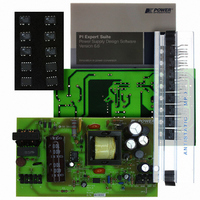
RDK-142
Manufacturer Part Number
RDK-142
Description
KIT REF DESIGN TOP HX FOR TOP258
Manufacturer
Power Integrations
Series
TOPSwitch®-HXr
Datasheet
1.RDK-142.pdf
(40 pages)
Specifications of RDK-142
Mfg Application Notes
TOPSwitch-HX Family Appl Note
Main Purpose
AC/DC, Primary Side
Outputs And Type
2, Non-Isolated
Power - Output
35W
Voltage - Output
5V, 12V
Current - Output
2.2A, 2A
Voltage - Input
90 ~ 265VAC
Regulator Topology
Flyback
Frequency - Switching
30kHz
Board Type
Fully Populated
Utilized Ic / Part
TOP258
Product
Accessories & Kits
Silicon Manufacturer
Power Integrations
Kit Application Type
Displays
Application Sub Type
LCD Monitor
Kit Contents
Samples, Fully Functional Reference Board And Complete Documentation
Rohs Compliant
Yes
Lead Free Status / RoHS Status
Lead free / RoHS Compliant
Other names
596-1193
07-Dec-07
RDR-142 35 W, TOP258PN Dual Output Supply
Output rectification for the 12 V output is provided by diode D7. Low ESR capacitors C13
and C14 provide filtering. Inductor L2 and capacitor C15 form a second stage filter that
significantly attenuates the switching ripple and ensures low ripple at the output.
Snubber networks comprising R11, C12 and R12, and C16 damp high frequency ringing
across diodes D7 and D8, which results from leakage inductance of the transformer
windings and the secondary trace inductances.
4.4 Output Feedback
Output voltage is controlled using the shunt regulator TL431 (U3). Diode D9, capacitor
C20 and resistor R16 form the soft finish circuit. At start-up, capacitor C20 is discharged.
As the output voltage starts rising, current flows into the optocoupler diode (U2A) via
resistor R13 and diode D9. This provides feedback to the circuit on the primary side.
The current in the optocoupler diode U2A gradually decreases as capacitor C20 charges
and U3 becomes operational. This ensures that the output voltage increases gradually
and settles to the final value without any overshoot. Resistor R16 provides a discharge
path for C20 into the load at power down. Diode D9 isolates C20 from the feedback
circuit after startup.
Resistor R18, R20 and R21 form a voltage divider network that senses the output voltage
from both the outputs for better cross-regulation. Resistor R19 and Zener VR3 improve
cross regulation when only the 5 V output is loaded, which results in the 12 V output
operating at the higher end of the specification.
Resistors R13, R17 and capacitor C21 set the frequency response of the feedback
circuit. Capacitor C19 and resistor R14 form the phase boost network that provides
adequate phase margin to ensure stable operation over the entire operating voltage
range.
Resistor R15 provides the bias current required by the IC U3 and is placed in parallel with
U2A to ensure that the bias current to the IC does not become a part of the feedback
current. Resistor R13 sets the overall DC loop gain and limits the current through U2A
during transient conditions.
Power Integrations
Tel: +1 408 414 9200 Fax: +1 408 414 9201
Page 9 of 40
www.powerint.com


