RDK-142 Power Integrations, RDK-142 Datasheet - Page 2
RDK-142
Manufacturer Part Number
RDK-142
Description
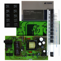
KIT REF DESIGN TOP HX FOR TOP258
Manufacturer
Power Integrations
Series
TOPSwitch®-HXr
Datasheet
1.RDK-142.pdf
(40 pages)
Specifications of RDK-142
Mfg Application Notes
TOPSwitch-HX Family Appl Note
Main Purpose
AC/DC, Primary Side
Outputs And Type
2, Non-Isolated
Power - Output
35W
Voltage - Output
5V, 12V
Current - Output
2.2A, 2A
Voltage - Input
90 ~ 265VAC
Regulator Topology
Flyback
Frequency - Switching
30kHz
Board Type
Fully Populated
Utilized Ic / Part
TOP258
Product
Accessories & Kits
Silicon Manufacturer
Power Integrations
Kit Application Type
Displays
Application Sub Type
LCD Monitor
Kit Contents
Samples, Fully Functional Reference Board And Complete Documentation
Rohs Compliant
Yes
Lead Free Status / RoHS Status
Lead free / RoHS Compliant
Other names
596-1193


Table of Contents
1
2
3
4
5
6
7
8
9
10
11
12
13
14
15
4.1
4.2
4.3
4.4
4.5
6.1
6.2
6.3
6.4
6.5
8.1
8.2
8.3
11.1
11.2
11.3
11.4
11.5
11.6
13.1
13.2
Introduction.................................................................................................................4
Power Supply Specification ........................................................................................5
Schematic...................................................................................................................6
Circuit Description ......................................................................................................7
Bill of Materials .........................................................................................................11
Transformer Specification.........................................................................................13
Design Spreadsheet .................................................................................................16
Performance Data ....................................................................................................20
8.1.1
Regulation ................................................................................................................24
9.1.1
9.1.2
9.1.3
11.6.1
11.6.2
Thermal Performance ...........................................................................................27
Waveforms............................................................................................................28
Line Surge.............................................................................................................35
Control Loop Measurements.................................................................................36
Conducted EMI .....................................................................................................37
Revision History ....................................................................................................38
Input EMI Filtering ...............................................................................................7
TOPSwitch-HX Primary .......................................................................................7
Output Rectification .............................................................................................8
Output Feedback.................................................................................................9
PCB Layout .......................................................................................................10
Electrical Diagram .............................................................................................13
Electrical Specifications.....................................................................................13
Materials............................................................................................................13
Transformer Build Diagram ...............................................................................14
Transformer Construction..................................................................................15
Efficiency ...........................................................................................................20
No-load Input Power..........................................................................................22
Available Standby Output Power.......................................................................23
Drain Voltage and Current, Normal Operation...................................................28
Output Voltage Start-up Profile..........................................................................28
Drain Voltage and Current Start-up Profile ........................................................30
Load Transient Response (75% to 100% Load Step) .......................................31
Output Over-voltage Protection .........................................................................32
Output Ripple Measurements............................................................................33
90 VAC Maximum Load.....................................................................................36
265 VAC Maximum Load...................................................................................36
Power Integrations
Tel: +1 408 414 9200 Fax: +1 408 414 9201
www.powerint.com
Active Mode CEC Measurement Data........................................................20
Load ...........................................................................................................24
Line ............................................................................................................25
Cross Regulation Matrix .............................................................................26
Ripple Measurement Technique ................................................................33
Measurement Results ................................................................................34
Page 2 of 40
Related parts for RDK-142
Image
Part Number
Description
Manufacturer
Datasheet
Request
R

Part Number:
Description:
KIT REF DESIGN FOR LNK457D
Manufacturer:
Power Integrations
Datasheet:

Part Number:
Description:
REFERENCE DESIGN LINKSWITCH-PH
Manufacturer:
Power Integrations
Datasheet:

Part Number:
Description:
KIT REF DESIGN FOR LNK403EG
Manufacturer:
Power Integrations
Datasheet:

Part Number:
Description:
KIT REF DESIGN FOR LNK406EG
Manufacturer:
Power Integrations
Datasheet:

Part Number:
Description:
KIT REF DESIGN LINKSWITCH-CV
Manufacturer:
Power Integrations
Datasheet:

Part Number:
Description:
KIT REF DESIGN LINKSWITCH 2
Manufacturer:
Power Integrations
Datasheet:

Part Number:
Description:
Specifications: Family: Eval Boards - DC/DC & AC/DC (Off-Line) SMPS ; Series: HiperLCS™ ; Main Purpose: DC/DC, Step Down ; Outputs and Type: 1, Isolated ; Power - Output: 150W ; Voltage - Output: 24V ; Current - Output: 6.25A ; Voltage - Input:
Manufacturer:
Power Integrations, Inc.
Datasheet:

Part Number:
Description:
KIT DESIGN REF TINYSWITCH-III
Manufacturer:
Power Integrations
Datasheet:

Part Number:
Description:
KIT DESIGN REF LINKSWITCH LP
Manufacturer:
Power Integrations
Datasheet:

Part Number:
Description:
KIT REF DESIGN LED LINKSWITCH TN
Manufacturer:
Power Integrations
Datasheet:
Part Number:
Description:
KIT REF DESIGN PG LINKSWITCH-II
Manufacturer:
Power Integrations
Datasheet:
Part Number:
Description:
REFERENCE DESIGN LINKSWITCH-PL
Manufacturer:
Power Integrations
Datasheet:
Part Number:
Description:
REFERENCE DESIGN LINKSWITCH-PH
Manufacturer:
Power Integrations
Datasheet:

Part Number:
Description:
KIT REF DESIGN 36-72W MOTOR DRVR
Manufacturer:
Power Integrations
Datasheet:
Part Number:
Description:
Specifications: Manufacturer: Power Integrations ; Output Voltage: 380 VDC ; Input / Supply Voltage (Max): 264 VAC ; Input / Supply Voltage (Min): 90 VAC ; Mounting Style: Through Hole ; Output Current: 0.913 A ; Output Power: 347 W
Manufacturer:
Power Integrations, Inc.