CDB5376 Cirrus Logic Inc, CDB5376 Datasheet - Page 18
CDB5376
Manufacturer Part Number
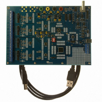
CDB5376
Description
EVALUATION BOARD FOR CS5376
Manufacturer
Cirrus Logic Inc
Datasheets
1.CS5371A-ISZR.pdf
(32 pages)
2.CS4373A-ISZ.pdf
(34 pages)
3.CS5376A-IQZR.pdf
(106 pages)
4.CDB5378.pdf
(16 pages)
5.CDB5376.pdf
(80 pages)
6.CDB5376.pdf
(16 pages)
Specifications of CDB5376
Main Purpose
Seismic Evaluation System
Embedded
Yes, MCU, 8-Bit
Utilized Ic / Part
CS3301A, CS3302A, CS4373A, CS5372A, CS5376A
Primary Attributes
Quad Digital Filter
Secondary Attributes
Graphical User Interface, SPI™ & USB Interfaces
Processor To Be Evaluated
CS330x, CS4373A, CS537x
Interface Type
USB
Lead Free Status / RoHS Status
Contains lead / RoHS non-compliant
Lead Free Status / RoHS Status
Lead free / RoHS Compliant, Contains lead / RoHS non-compliant
Other names
598-1778


4. POWER MODES
The CS4373A has four power modes. AC test
modes and DC test modes are operational
modes, while the power down and sleep
modes are non-operational, standby modes.
4.1 Power Down
If MCLK is stopped, an internal loss-of-clock
detection circuit automatically places the
CS4373A into power down. Power down is in-
dependent of the MODE and ATT pin settings,
and is automatically invoked after approxi-
mately 40
In power down the AC and DC test circuitry is
inactive and the analog outputs are high im-
pedance. When used with the CS5376A digital
filter, the CS4373A is powered down immedi-
ately after reset since MCLK is disabled by de-
fault.
4.2 Sleep Modes
With MCLK enabled, selecting either of the
sleep
CS4373A into a micropower sleep state. Fol-
lowing completion of the AC and DC system
self-tests, the CS4373A is typically set into
18
modes
µ
s without an incoming MCLK edge.
(MODE 0, 7)
Figure 7. Power Mode Diagram
places
AC TEST MODES
MODE = 1, 2, 3, 6
MCLK = ON
the
POWER DOWN
SLEEP MODES
MODE = XXX
MCLK = OFF
MODE = 0, 7
MCLK = ON
sleep mode for normal data acquisition. In
sleep mode the AC and DC test circuitry is in-
active and the analog outputs are high imped-
ance.
4.3 AC Test Modes
With MCLK and TDATA active, selecting an
AC test mode (MODE 1, 2, 3, 6) causes the
CS4373A to output AC waveforms on the en-
abled analog outputs. AC test modes use the
low-power ∆Σ circuitry in the CS4373A to cre-
ate precision differential or common mode an-
alog AC output signals from the encoded
digital test bit stream (TBS) input.
4.4 DC Test Modes
With MCLK active, selecting a DC test mode
(MODE 4, 5) causes the CS4373A to generate
precision DC voltages on the analog outputs.
DC test modes use switch-capacitor level-
shifting buffer circuitry in the CS4373A to cre-
ate differential or common mode DC analog
output voltages from the voltage reference in-
put.
DC TEST MODES
MODE = 4, 5
MCLK = ON
CS4373A
DS699F2
Related parts for CDB5376
Image
Part Number
Description
Manufacturer
Datasheet
Request
R

Part Number:
Description:
Development Kit
Manufacturer:
Cirrus Logic Inc
Datasheet:
Part Number:
Description:
Development Kit
Manufacturer:
Cirrus Logic Inc
Datasheet:


Part Number:
Description:
High-efficiency PFC + Fluorescent Lamp Driver Reference Design
Manufacturer:
Cirrus Logic Inc
Datasheet:
Part Number:
Description:
Development Kit
Manufacturer:
Cirrus Logic Inc
Datasheet:
Part Number:
Description:
Development Kit
Manufacturer:
Cirrus Logic Inc
Datasheet:

Part Number:
Description:
Development Kit
Manufacturer:
Cirrus Logic Inc
Datasheet:
Part Number:
Description:
Development Kit
Manufacturer:
Cirrus Logic Inc
Datasheet:
Part Number:
Description:
Development Kit
Manufacturer:
Cirrus Logic Inc
Datasheet:
Part Number:
Description:
Development Kit
Manufacturer:
Cirrus Logic Inc
Datasheet:

Part Number:
Description:
EVALUATION BOARD FOR CS8427
Manufacturer:
Cirrus Logic Inc
Datasheet:

Part Number:
Description:
BOARD EVAL FOR CS8416 RCVR
Manufacturer:
Cirrus Logic Inc
Datasheet:

Part Number:
Description:
EVALUATION BOARD FOR CS8420
Manufacturer:
Cirrus Logic Inc
Datasheet:

Part Number:
Description:
KIT DEVELOPMENT EP9315 ARM9
Manufacturer:
Cirrus Logic Inc
Datasheet:

Part Number:
Description:
KIT DEVELOPMENT EP9302 ARM9
Manufacturer:
Cirrus Logic Inc
Datasheet: