DC-VIDEO-TVP5146N Altera, DC-VIDEO-TVP5146N Datasheet - Page 32
DC-VIDEO-TVP5146N
Manufacturer Part Number
DC-VIDEO-TVP5146N
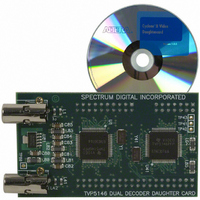
Description
VIDEO DAUGHTER CARD
Manufacturer
Altera
Series
Stratix® IIIr
Datasheets
1.EP3SL150F780C4N.pdf
(16 pages)
2.EP3SL150F780C4N.pdf
(332 pages)
3.DC-VIDEO-TVP5146N.pdf
(58 pages)
Specifications of DC-VIDEO-TVP5146N
Main Purpose
Video, Daughter Card
Embedded
No
Utilized Ic / Part
Altera Dev Kits
Primary Attributes
Dual Composite Video Input - NTSC or PAL
Secondary Attributes
10-bit BT.656 Output, Compatible with Expansion Connector, Standard on Most Altera Development Kits
Lead Free Status / RoHS Status
Lead free / RoHS Compliant
Other names
544-1704


1–32
Figure 1–5. Output Register Clock to Output Timing Diagram
Stratix III Device Handbook, Volume 2
Datain
Clock
Figure 1–4
Figure 1–4. Input Register Setup and Hold Timing Diagram
For output timing, different I/O standards require different baseline loading
techniques for reporting timing delays. Altera characterizes timing delays with the
required termination for each I/O standard and with 0 pF (except for PCI and PCI-X,
which use 10 pF) loading. The timing is specified up to the output pin of the FPGA
device. The Quartus II software calculates I/O timing for each I/O standard with a
default baseline loading as specified by the I/O standards.
The following measurements are made during device characterization. Altera
measures clock-to-output delays (t
maximum temperature (PVT) for default loading conditions listed in
page
Stratix III devices.
The t
+ delay from the clock pad to the I/O output register
+ IOE output register clock-to-output delay
+ delay from the output register to the output pin
Figure 1–5
Simulation using IBIS models is required to determine the delays on the PCB traces in
addition to the output pin delay timing reported by the Quartus II software and the
timing model in the Stratix III Device Handbook. Perform the following steps:
1. Simulate the output driver of choice into the generalized test setup using values
2. Record the time to V
3. Simulate the output driver of choice into the actual PCB trace and load using the
4. Record the time to V
from
appropriate IBIS model or capacitance value to represent the load.
co
1–34. The following equation describes clock-pin-to-output-pin timing for
from the clock pin to the I/O pin =
Table
Clock pad to output
shows the setup and hold timing diagram for input registers.
shows the output register clock to output timing diagram.
Register delay
1–37.
MEAS
MEAS
at the far end of the PCB trace.
at the far end of the PCB trace.
Output Register
Input Clock Delay
Input Data Delay
micro t
Chapter 1: Stratix III Device Datasheet: DC and Switching Characteristics
co
CO
) at worst-case process, minimum voltage, and
Output Register to
output pin delay
micro t
micro t
su
h
© July 2010 Altera Corporation
Output
Table 1–37 on
I/O Timing
Related parts for DC-VIDEO-TVP5146N
Image
Part Number
Description
Manufacturer
Datasheet
Request
R

Part Number:
Description:
CYCLONE II STARTER KIT EP2C20N
Manufacturer:
Altera
Datasheet:


Part Number:
Description:
CPLD, EP610 Family, ECMOS Process, 300 Gates, 16 Macro Cells, 16 Reg., 16 User I/Os, 5V Supply, 35 Speed Grade, 24DIP
Manufacturer:
Altera Corporation
Datasheet:
Part Number:
Description:
CPLD, EP610 Family, ECMOS Process, 300 Gates, 16 Macro Cells, 16 Reg., 16 User I/Os, 5V Supply, 15 Speed Grade, 24DIP
Manufacturer:
Altera Corporation
Datasheet:
Part Number:
Description:
Manufacturer:
Altera Corporation
Datasheet:
Part Number:
Description:
CPLD, EP610 Family, ECMOS Process, 300 Gates, 16 Macro Cells, 16 Reg., 16 User I/Os, 5V Supply, 30 Speed Grade, 24DIP
Manufacturer:
Altera Corporation
Datasheet:
Part Number:
Description:
High-performance, low-power erasable programmable logic devices with 8 macrocells, 10ns
Manufacturer:
Altera Corporation
Datasheet:
Part Number:
Description:
High-performance, low-power erasable programmable logic devices with 8 macrocells, 7ns
Manufacturer:
Altera Corporation
Datasheet:
Part Number:
Description:
Classic EPLD
Manufacturer:
Altera Corporation
Datasheet:
Part Number:
Description:
High-performance, low-power erasable programmable logic devices with 8 macrocells, 10ns
Manufacturer:
Altera Corporation
Datasheet:
Part Number:
Description:
Manufacturer:
Altera Corporation
Datasheet:
Part Number:
Description:
Manufacturer:
Altera Corporation
Datasheet:
Part Number:
Description:
Manufacturer:
Altera Corporation
Datasheet:
Part Number:
Description:
CPLD, EP610 Family, ECMOS Process, 300 Gates, 16 Macro Cells, 16 Reg., 16 User I/Os, 5V Supply, 25 Speed Grade, 24DIP
Manufacturer:
Altera Corporation
Datasheet: