STEVAL-ISF001V1 STMicroelectronics, STEVAL-ISF001V1 Datasheet - Page 8
STEVAL-ISF001V1
Manufacturer Part Number
STEVAL-ISF001V1
Description
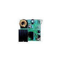
BOARD EVAL FOR L6563/STW55NM60N
Manufacturer
STMicroelectronics
Type
MOSFET & Power Driverr
Datasheets
1.STW55NM60N.pdf
(12 pages)
2.L6563ATR.pdf
(39 pages)
3.STEVAL-ISF001V1.pdf
(20 pages)
4.STEVAL-ISF001V1.pdf
(4 pages)
Specifications of STEVAL-ISF001V1
Main Purpose
Power Management, Power Factor Correction
Embedded
No
Utilized Ic / Part
L6563
Primary Attributes
3 kW, 400 V Out, FOT(Fixed Off Time Control), 240 VAC (185 ~ 265 Vrms)
Secondary Attributes
Iout Max 7.5 A
Product
Power Management Modules
Lead Free Status / RoHS Status
Lead free / RoHS Compliant
For Use With/related Products
STW55NM60N
Other names
497-8850


PFC board connection
3
Note:
Caution:
Note:
3.1
8/20
PFC board connection
The PFC board is manufactured ready to use. Using jumper J3, the supply of the driver
L6563 can be connected directly to the supply generated by the auxiliary winding present on
the boost inductor or to an isolated low-voltage external supply. This option can be used to
debug or to test an inductor not equipped with an auxiliary winding. Set jumper J3 to
position 2-3 to use the standard auxiliary power supply already present on the board. If an
external supply is used, set J3 to position 1-2 and connect a 15 V DC supply capable of at
least 100 mA to J4 (+15 on J4 pin1, ground on J4 pin2). Connect the board to the AC power
supply.
Use a suitable cable, in terms of insulation and cross-section, to be able to conduct the
current from the supply according to the load connected to the output port.
Connect the output port to the load.
Even if the system is able to start up and maintain the output voltage regulated to the target
value, also under open-load condition, the technical specification in terms of PF and THD
cannot be guaranteed.
The systems accept a minimum power load to work properly.
Supply the PFC board with a sinusoidal supply voltage with amplitude in the range of 185
Vrms to 265 Vrms. The power source has to be able to supply the power required by the
system, according to the output load the user intends to connect to the output port.
Do not supply the system with a voltage value higher than 265 Vrms, as risk of serious
damage to the board and to property is present in this case. Do not supply the system with a
voltage below the minimum allowed, 185 Vrms, as the systems cannot start or operate
properly in this condition.
Low voltage supply and maximum output load present the worst operating conditions for the
system and sufficient cooling is mandatory.
STEVAL-ISF001V1 description
The demonstration board STEVAL-ISF001V1 developed by STMicroelectronics provides a
compact, and ready-to-use solution for the implementation of a simple PFC system able to
supply load with power close to the maximum delivered in most typical domestic
installations. For such a range of power the use of a continuous-mode PFC operation
becomes mandatory to drain from the mains a current with an rms value which does not
exceed the maximum allowed from the metering system and to have a reasonable size of
the devices involved in the system’s operations.
The use of a standard continuous-mode driver chip necessitates using a more expensive
and complex driver with all the required passive components.
STMicroelectronics has patented a solution that allows using a simple driver, designed for a
transition-mode operation, in a fixed-off-time, variable frequency, PWM modulation. This
kind of modulation gives a current on the boost inductor of the PFC that is comparable with
the current of a typical continuous-mode modulation.
Modulating T
to maintain continuous current on the inductor around a sinusoidal envelope. As a
ON
and fixing T
OFF
Doc ID 15337 Rev 1
of the PWM signal applied to the main switch, it is possible
UM0673
Related parts for STEVAL-ISF001V1
Image
Part Number
Description
Manufacturer
Datasheet
Request
R

Part Number:
Description:
BOARD RGB CTR ST7,STP08C596MTR
Manufacturer:
STMicroelectronics
Datasheet:

Part Number:
Description:
Power Management IC Development Tools Full Speed USB to RS232 Bridge Demo
Manufacturer:
STMicroelectronics
Datasheet:
Part Number:
Description:
Power Management IC Development Tools 2.5W solar eval BRD USB SPV1040 LD39050
Manufacturer:
STMicroelectronics
Datasheet:

Part Number:
Description:
BOARD EVAL FOR MEMS SENSORS
Manufacturer:
STMicroelectronics
Datasheet:

Part Number:
Description:
KIT DEV STARTER ST10F276Z5
Manufacturer:
STMicroelectronics
Datasheet:

Part Number:
Description:
BOARD EVAL HDMI $ VIDEO SWITCH
Manufacturer:
STMicroelectronics
Datasheet:

Part Number:
Description:
BOARD DEMO ACCELEROMETER DIL24
Manufacturer:
STMicroelectronics
Datasheet:

Part Number:
Description:
BOARD STLM75/STDS75/ST72F651
Manufacturer:
STMicroelectronics
Datasheet:

Part Number:
Description:
EVAL BOARD 3AXIS MEMS ACCELLRMTR
Manufacturer:
STMicroelectronics
Datasheet:

Part Number:
Description:
BOARD EVAL 8BIT MICRO + TDE1708
Manufacturer:
STMicroelectronics
Datasheet:
Part Number:
Description:
STMicroelectronics [RIPPLE-CARRY BINARY COUNTER/DIVIDERS]
Manufacturer:
STMicroelectronics
Datasheet:
Part Number:
Description:
STMicroelectronics [LIQUID-CRYSTAL DISPLAY DRIVERS]
Manufacturer:
STMicroelectronics
Datasheet:
Part Number:
Description:
BOARD EVAL FOR MEMS SENSORS
Manufacturer:
STMicroelectronics
Datasheet: