STEVAL-ISF001V1 STMicroelectronics, STEVAL-ISF001V1 Datasheet
STEVAL-ISF001V1
Specifications of STEVAL-ISF001V1


Related parts for STEVAL-ISF001V1


STEVAL-ISF001V1 Summary of contents
Page 1
... Introduction The power board STEVAL-ISF001V1 PFC designed for industrial and domestic applications. The board must be used for demonstration purposes in order to evaluate the potential of the FOT (fixed-off-time control, patented by ST) to implement a high-power PFC with performance comparable to a standard continuous-mode PFC, but using a simpler controller chip originally designed for TM (transition-mode) PFC operating conditions ...
Page 2
... Power board 3 kW FOT PFC installation . . . . . . . . . . . . . . . . . . . . . . . . . . 5 2.2.1 2.2.2 2.3 Hardware layout . . . . . . . . . . . . . . . . . . . . . . . . . . . . . . . . . . . . . . . . . . . . . 6 2.4 Environmental considerations . . . . . . . . . . . . . . . . . . . . . . . . . . . . . . . . . . 7 3 PFC board connection . . . . . . . . . . . . . . . . . . . . . . . . . . . . . . . . . . . . . . . 8 3.1 STEVAL-ISF001V1 description . . . . . . . . . . . . . . . . . . . . . . . . . . . . . . . . . 8 3.2 STEVAL-ISF001V1 circuit description . . . . . . . . . . . . . . . . . . . . . . . . . . . . 9 4 BOM and schematics . . . . . . . . . . . . . . . . . . . . . . . . . . . . . . . . . . . . . . . 11 5 Experimental measurements . . . . . . . . . . . . . . . . . . . . . . . . . . . . . . . . . 14 6 Revision history . . . . . . . . . . . . . . . . . . . . . . . . . . . . . . . . . . . . . . . . . . . 19 2/20 Power board 3 kW FOT PFC intended use . . . . . . . . . . . . . . . . . . . . . . . 5 Electronic connection ...
Page 3
... Line, inductor, switch and diode current in TM PFC . . . . . . . . . . . . . . . . . . . . . . . . . . . . . . . 1 Figure 3. STEVAL-ISF001V1 demonstration board . . . . . . . . . . . . . . . . . . . . . . . . . . . . . . . . . . . . . . . 4 Figure 4. Power board 3 kW FOT PFC STEVAL-ISF001V1 (top view Figure 5. Schematic of the STEVAL-ISF001V1 board . . . . . . . . . . . . . . . . . . . . . . . . . . . . . . . . . . . . 13 Figure 6. Common-mode inductor L1 (MAGNETICA 1745.0005) technical sheet Figure 7. Common-mode inductor L2 (MAGNETICA 1951.0001) technical sheet Figure 8. ...
Page 4
... Board description 1 Board description The STEVAL-ISF001V1 can be used for several kinds of applications: ● Inverter for motor control ● Air conditioning system ● Welding machine DC power supply section. This demonstration board offers customization options as well, making it an excellent choice as an original platform for a more complete and dedicated system. Special care has been taken during the layout process to provide a very low level of interference ...
Page 5
... Warning: This board must be used only in a power laboratory only by engineers and technicians who are experienced in power electronics technology and under protection. STMicroelectronics is not responsible for damages to property nor personal injury. 2.1.1 Power board 3 kW FOT PFC intended use The power board 3 kW FOT PFC is designed for demonstration purposes only and shall not be used for electrical installation or machinery ...
Page 6
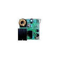
... Hardware layout Figure 4. Power board 3 kW FOT PFC STEVAL-ISF001V1 (top view) The mains input connector is present on the right side of the board. Connect a sinusoidal supply voltage with amplitude in the range of 185 Vrms to 265 Vrms. The power source has to be able to supply the power required by the system, according to the output load the user intends to connect on the output port ...
Page 7
... It is preferable to test the kit in ambient temperature not higher than 45 degrees Celsius. 2.4 Environmental considerations The STEVAL-ISF001V1 must only be used in a power laboratory. The high voltage involved in the system presents a serious shock hazard. If the board used to measure or capture waveforms or any other interaction between the board and laboratory equipment, an AC-isolated power supply has to be used ...
Page 8
... STEVAL-ISF001V1 description The demonstration board STEVAL-ISF001V1 developed by STMicroelectronics provides a compact, and ready-to-use solution for the implementation of a simple PFC system able to supply load with power close to the maximum delivered in most typical domestic installations. For such a range of power the use of a continuous-mode PFC operation ...
Page 9
... Driver with inductor saturation detection ● Optimized EMC input filter. 3.2 STEVAL-ISF001V1 circuit description Figure 5 shows the entire electronic schematic. Starting from the input section, a common-mode EMC filter is fitted in order to be compliant with the EMC regulations concerning industrial and domestic applications. (EN55014 and EN55022) ...
Page 10
PFC board connection The chosen switching devices are two Power MOSFETs, MDmesh™ II family, STW55NM60N. These two Power MOSFETs placed in parallel assure a low R the conduction power losses. Good efficiency and good thermal behavior of the system can ...
Page 11
UM0673 4 BOM and schematics Table 1. Bill of material Item Qty Reference ...
Page 12
BOM and schematics Table 1. Bill of material (continued) Item Qty Reference R7,R13,R26 R9,R10,R11 43 3 R12,R16,R17 ...
Page 13
... UM0673 Figure 5. Schematic of the STEVAL-ISF001V1 board Doc ID 15337 Rev 1 BOM and schematics AM01975v1 13/20 ...
Page 14
Experimental measurements 5 Experimental measurements Table below shows the performance of the PFC board during lab testing. Table 2. Lab preliminary electrical measurements Low-power range Medium-power range High-power range Full load 14/20 185 Vac Vout 406 Iout 0.75 Pout 306 ...
Page 15
... Product: Common Mode Inductor 2x2mH 18A Customer: T YPICAL APPLICATION D ISTURB SUPPRESSION ON 270V . MAX SCHEMATIC 1 4 SETUP OF MEASURE C M OMMON ODE D M IFFERENTIAL ODE Product Technical Specification STMicroelectronics T ECHNICAL DATA AC/DC POWER LINE OF I NDUCTANCE ( MEASURE R ESISTANCE ( MEASURE D L EAKAGE ( MEASURE O PERATING 2 (F 50-60H O ...
Page 16
Experimental measurements Figure 7. Common-mode inductor L2 (MAGNETICA 1951.0001) technical sheet STP 03 Product: Common Mode Inductor 2x220uH/18A ST Microelectronics Customer: TYPICAL APPLICATION EMC SUPPRESSION ON . MAX SCHEMATIC 1 4 SETUP OF MEASURE C M OMMON ODE D M ...
Page 17
... UM0673 Figure 8. Common-mode inductor L3 (MAGNETICA 1929.0001) technical sheet STP 03 Product: Common Mode Inductor 2x30uH/8A STMicroelectronics Customer: T YPICAL APPLICATION D ISTURB SUPPRESSION ON 400V . MAX SCHEMATIC 1 4 SETUP OF MEASURE C M OMMON ODE IFFERENTIAL ODE 1 2 Product Technical Specification T ECHNICAL DATA AC/DC POWER LINE OF I NDUCTANCE ...
Page 18
... NDUCTOR FOR CONVERTER PULL AND FULL S CHEMATIC 1-2-3 4-5-6 INDUCTANCE VS CURRENT 100% L 10% 0 (*) PIN (*)P IN WITH THE SAME SUBSCRIPT MUST BE CONNECTED TOGETHER ON 18/20 Product Technical Specification STMicroelectronics T PPLICATION UCK OOST AND UCK OOST NDUCTANCE , - , - SUITABLE ALSO IN HALF BRIDGE PUSH (M - BRIDGE APPLICATIONS R ...
Page 19
UM0673 6 Revision history Table 3. Document revision history Date 24-Sep-2009 Revision 1 Initial release. Doc ID 15337 Rev 1 Revision history Changes 19/20 ...
Page 20
... Information in this document is provided solely in connection with ST products. STMicroelectronics NV and its subsidiaries (“ST”) reserve the right to make changes, corrections, modifications or improvements, to this document, and the products and services described herein at any time, without notice. All ST products are sold pursuant to ST’s terms and conditions of sale. ...