C8051F700-TB Silicon Laboratories Inc, C8051F700-TB Datasheet - Page 51
C8051F700-TB
Manufacturer Part Number
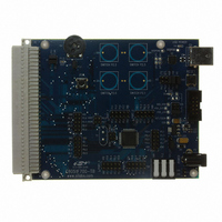
C8051F700-TB
Description
BOARD PROTOTYPE WITH C8051F700
Manufacturer
Silicon Laboratories Inc
Datasheets
1.C8051F700-TB.pdf
(1 pages)
2.C8051F700-TB.pdf
(306 pages)
3.C8051F700-TB.pdf
(18 pages)
Specifications of C8051F700-TB
Accessory Type
Target Board
Processor To Be Evaluated
C8051F700
Processor Series
C8051F7xx
Interface Type
USB
Operating Supply Voltage
7 V to 15 V
Lead Free Status / RoHS Status
Lead free / RoHS Compliant
For Use With/related Products
C8051F7xx
Lead Free Status / Rohs Status
Lead free / RoHS Compliant
Other names
336-1637
C8051F700
C8051F700


Table 9.8. Capacitive Sense Electrical Characteristics
V
Parameter
Single Conversion Time
Number of Channels
Capacitance per Code
External Capacitive Load
External Series Impedance
Quantization Noise
Power Supply Current
Notes:
DD
1. Conversion time is specified with the default configuration.
2. RMS Noise is equivalent to one standard deviation. Peak-to-peak noise encompasses ±3.3 standard
3. Includes only current from regulator, CS module, and MCU in suspend mode.
= 1.8 to 3.6 V; T
deviations. The RMS noise value is specified with the default configuration.
A
12
= –40 to +85 °C unless otherwise specified.
1
Wake-on-CS threshold (suspend mode
with regulator and CS module on)
CS module alone, maximum code
CS module bias current, 25 °C
CS0CG = 111b (Default)
CS0CG = 111b (Default)
Default Configuration
13-bit Mode (default)
64-pin Packages
48-pin Packages
32-pin Packages
24-pin Packages
CS0CG = 000b
Peak-to-Peak
output, 25 °C
Conditions
12-bit Mode
14-bit Mode
16-bit Mode
RMS
Rev. 1.0
3
Min
20
21
23
26
C8051F70x/71x
—
—
—
—
—
—
—
—
—
Typ
130
38
27
26
18
29
31
33
38
20
50
90
—
—
—
1
3
Max
42.5
145
500
105
40
45
50
45
50
60
—
—
—
Channels
Units
k
µA
µA
µA
pF
pF
µs
fF
fF
fF
51
Related parts for C8051F700-TB
Image
Part Number
Description
Manufacturer
Datasheet
Request
R

Part Number:
Description:
SMD/C°/SINGLE-ENDED OUTPUT SILICON OSCILLATOR
Manufacturer:
Silicon Laboratories Inc
Part Number:
Description:
Manufacturer:
Silicon Laboratories Inc
Datasheet:
Part Number:
Description:
N/A N/A/SI4010 AES KEYFOB DEMO WITH LCD RX
Manufacturer:
Silicon Laboratories Inc
Datasheet:
Part Number:
Description:
N/A N/A/SI4010 SIMPLIFIED KEY FOB DEMO WITH LED RX
Manufacturer:
Silicon Laboratories Inc
Datasheet:
Part Number:
Description:
N/A/-40 TO 85 OC/EZLINK MODULE; F930/4432 HIGH BAND (REV E/B1)
Manufacturer:
Silicon Laboratories Inc
Part Number:
Description:
EZLink Module; F930/4432 Low Band (rev e/B1)
Manufacturer:
Silicon Laboratories Inc
Part Number:
Description:
I°/4460 10 DBM RADIO TEST CARD 434 MHZ
Manufacturer:
Silicon Laboratories Inc
Part Number:
Description:
I°/4461 14 DBM RADIO TEST CARD 868 MHZ
Manufacturer:
Silicon Laboratories Inc
Part Number:
Description:
I°/4463 20 DBM RFSWITCH RADIO TEST CARD 460 MHZ
Manufacturer:
Silicon Laboratories Inc
Part Number:
Description:
I°/4463 20 DBM RADIO TEST CARD 868 MHZ
Manufacturer:
Silicon Laboratories Inc
Part Number:
Description:
I°/4463 27 DBM RADIO TEST CARD 868 MHZ
Manufacturer:
Silicon Laboratories Inc
Part Number:
Description:
I°/4463 SKYWORKS 30 DBM RADIO TEST CARD 915 MHZ
Manufacturer:
Silicon Laboratories Inc
Part Number:
Description:
N/A N/A/-40 TO 85 OC/4463 RFMD 30 DBM RADIO TEST CARD 915 MHZ
Manufacturer:
Silicon Laboratories Inc
Part Number:
Description:
I°/4463 20 DBM RADIO TEST CARD 169 MHZ
Manufacturer:
Silicon Laboratories Inc