130-28176 Parallax Inc, 130-28176 Datasheet - Page 97
130-28176
Manufacturer Part Number
130-28176
Description
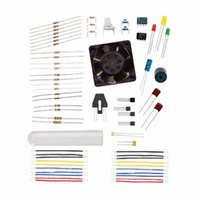
KIT PARTS PROCESS CONTROL
Manufacturer
Parallax Inc
Specifications of 130-28176
Accessory Type
Education Kit
Product
Microcontroller Accessories
Lead Free Status / RoHS Status
Contains lead / RoHS non-compliant
For Use With/related Products
Board of Education Full Kit
Lead Free Status / RoHS Status
Lead free / RoHS Compliant, Contains lead / RoHS non-compliant


The box labeled VCE should show different readings as you move your hand. If the VCE
readings do not change, something is amiss, and it is time to troubleshoot:
When all is working, move on:
√
√
√
√
√
√
√
√
√
√
√
√
Run the program DataMonitoring.bs2 from page 46.
Close the Debug Terminal.
Run StampPlot macro sic_pc_opto_plot.spm.
Connect and plot. Nothing will show or update initially on the main plotting
area.
Move your hand just a few inches toward and away from the QRB1114 sensor.
Check StampPlot to make sure you are connected, and plotting.
Try to reset or refresh the plot. (From the menus, select Plot → Reset Plot.)
Check your wiring to ensure you have not missed any connections.
Make sure the 100 Ω and 10 kΩ resistors are in their correct places.
Once the VCE readings update, move on to the next step.
Verify that 10 is selected from the RC(K) drop-down menu in StampPlot.
Using the ruler in Figure 4-4, position the front of the opto-reflective switch at
the 0 CM position as shown in Figure 4-4. For best results, use a book or
another object to raise the level of the ruler to be even with the device.
Figure 4-3
Opto-Reflective
Switch Wiring
Diagram
NOTE: the ACD0831
is installed “upside-
down” with Pin 1 at
the lower right in
this picture.
Related parts for 130-28176
Image
Part Number
Description
Manufacturer
Datasheet
Request
R

Part Number:
Description:
KIT PROPELLER EDU PROJECT PARTS
Manufacturer:
Parallax Inc
Datasheet:

Part Number:
Description:
KIT PARTS SMART SENSORS
Manufacturer:
Parallax Inc
Datasheet:


Part Number:
Description:
Microcontroller Modules & Accessories DISCONTINUED BY PARALLAX
Manufacturer:
Parallax Inc

Part Number:
Description:
BOOK UNDERSTANDING SIGNALS
Manufacturer:
Parallax Inc
Datasheet:


Part Number:
Description:
COMPETITION RING FOR SUMOBOT
Manufacturer:
Parallax Inc
Datasheet:


Part Number:
Description:
TEXT INFRARED REMOTE FOR BOE-BOT
Manufacturer:
Parallax Inc
Datasheet:
Part Number:
Description:
Microcontroller Modules & Accessories DISCONTINUED BY PARALLAX
Manufacturer:
Parallax Inc
Part Number:
Description:
BOOK UNDERSTANDING SIGNALS
Manufacturer:
Parallax Inc
Datasheet:
Part Number:
Description:
BOARD EXPERIMENT+LCD NX-1000
Manufacturer:
Parallax Inc
Datasheet:
Part Number:
Description:
IC MCU 2K FLASH 50MHZ SO-18
Manufacturer:
Parallax Inc
Datasheet: