130-28176 Parallax Inc, 130-28176 Datasheet - Page 80
130-28176
Manufacturer Part Number
130-28176
Description
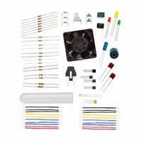
KIT PARTS PROCESS CONTROL
Manufacturer
Parallax Inc
Specifications of 130-28176
Accessory Type
Education Kit
Product
Microcontroller Accessories
Lead Free Status / RoHS Status
Contains lead / RoHS non-compliant
For Use With/related Products
Board of Education Full Kit
Lead Free Status / RoHS Status
Lead free / RoHS Compliant, Contains lead / RoHS non-compliant


Ideally, the output impedance of a device should be zero, and the input impedance should
be infinite to transfer the maximum voltage. Since we don't live in an ideal world, the
input impedance should be at least 10 times the value of the output impedance between
devices so that loading effects are not an issue. For example, if the input impedance of a
device is 1 MΩ, the output impedance of the device supplying it should be no more than
100 kΩ.
Using the transistor as an input from another device, a higher base resistance is desirable
to prevent loading and excessive current from the supplying device. Note that the control
of the transistor is dependent on base current. As long as R
voltage may be smaller or larger than Vdd. This allows a means to interface devices
operating at different supply voltages.
ACTIVITY #6: SWITCHING CONFIGURATION COMPARISONS
Figure 3-17 is a comparison of an Active-Low pushbutton switch and the common-
emitter transistor circuit that we have been using.
Figure 3-17 Switch Equivalent Common-Emitter Configuration
N. O. Active Low Switch with Pull-up
Impedance is similar to resistance, but also takes into account AC characteristics, which will
not be explored in this text.
Common-Emitter Configuration
B
is sized properly, this
Related parts for 130-28176
Image
Part Number
Description
Manufacturer
Datasheet
Request
R

Part Number:
Description:
KIT PROPELLER EDU PROJECT PARTS
Manufacturer:
Parallax Inc
Datasheet:

Part Number:
Description:
KIT PARTS SMART SENSORS
Manufacturer:
Parallax Inc
Datasheet:


Part Number:
Description:
Microcontroller Modules & Accessories DISCONTINUED BY PARALLAX
Manufacturer:
Parallax Inc

Part Number:
Description:
BOOK UNDERSTANDING SIGNALS
Manufacturer:
Parallax Inc
Datasheet:


Part Number:
Description:
COMPETITION RING FOR SUMOBOT
Manufacturer:
Parallax Inc
Datasheet:


Part Number:
Description:
TEXT INFRARED REMOTE FOR BOE-BOT
Manufacturer:
Parallax Inc
Datasheet:
Part Number:
Description:
Microcontroller Modules & Accessories DISCONTINUED BY PARALLAX
Manufacturer:
Parallax Inc
Part Number:
Description:
BOOK UNDERSTANDING SIGNALS
Manufacturer:
Parallax Inc
Datasheet:
Part Number:
Description:
BOARD EXPERIMENT+LCD NX-1000
Manufacturer:
Parallax Inc
Datasheet:
Part Number:
Description:
IC MCU 2K FLASH 50MHZ SO-18
Manufacturer:
Parallax Inc
Datasheet: