130-28176 Parallax Inc, 130-28176 Datasheet - Page 57
130-28176
Manufacturer Part Number
130-28176
Description
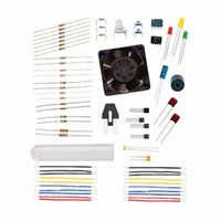
KIT PARTS PROCESS CONTROL
Manufacturer
Parallax Inc
Specifications of 130-28176
Accessory Type
Education Kit
Product
Microcontroller Accessories
Lead Free Status / RoHS Status
Contains lead / RoHS non-compliant
For Use With/related Products
Board of Education Full Kit
Lead Free Status / RoHS Status
Lead free / RoHS Compliant, Contains lead / RoHS non-compliant


LED
DigIn
ADC_CS
ADC_Clk
ADC_Dout
' -----[ Initialize ] -----------------------------------------------------
OUTPUT LED
PAUSE 1000
' -----[ Main Routine ]----------------------------------------------------
DO
LOOP
' -----[ Subroutines ]-----------------------------------------------------
ReadData:
RETURN
PlotData:
RETURN
Figure 3-2 shows an example test in which the threshold voltage was found to be
approximately 1.45 V. The digital trace at the top goes high and low as the analog
voltage goes above or below the threshold voltage.
GOSUB ReadData
LED = DigIn
GOSUB PlotData
PAUSE 500
LOW ADC_CS
DigDataIn = DigIn
SHIFTIN ADC_Dout, ADC_Clk, MSBPOST,[ADC_DataIn\9] ' Clock in data from ADC
HIGH ADC_CS
DEBUG IBIN DigDataIn,CR ' Plot indicated binary value
DEBUG "[",
√
√
√
√
√
Close the Debug Terminal.
Load StampPlot with the macro sic_pc_data_monitoring.spm
Connect and plot.
Adjust the potentiometer. The analog voltage and plotted value should change
accordingly.
HIGH/LOW status of P8.
Note the voltage at which the input P8 changes between HIGH and LOW logic
levels. This is the threshold voltage.
DEC ADC_DataIn, ' Analog data
",*,.0196]",CR
PIN 0
PIN 8
PIN 13
PIN 14
PIN 15
LED
' Read ADC 0831
' Enable chip
' Read digital input value to coincide with ADC read
' Disable ADC
' Send data to StampPlot
' Bracket for StampPlot math operation
' Convert ADC value to voltage by StampPlot
' LED output pin
' Digital input pin monitored
' ADC Chip Select pin
' ADC Clock pin
' ADC Data output
' Set LED as output
' Allow connection to stabilize
1
, on the BASIC Stamp output pin P0, indicates the
Related parts for 130-28176
Image
Part Number
Description
Manufacturer
Datasheet
Request
R

Part Number:
Description:
KIT PROPELLER EDU PROJECT PARTS
Manufacturer:
Parallax Inc
Datasheet:

Part Number:
Description:
KIT PARTS SMART SENSORS
Manufacturer:
Parallax Inc
Datasheet:


Part Number:
Description:
Microcontroller Modules & Accessories DISCONTINUED BY PARALLAX
Manufacturer:
Parallax Inc

Part Number:
Description:
BOOK UNDERSTANDING SIGNALS
Manufacturer:
Parallax Inc
Datasheet:


Part Number:
Description:
COMPETITION RING FOR SUMOBOT
Manufacturer:
Parallax Inc
Datasheet:


Part Number:
Description:
TEXT INFRARED REMOTE FOR BOE-BOT
Manufacturer:
Parallax Inc
Datasheet:
Part Number:
Description:
Microcontroller Modules & Accessories DISCONTINUED BY PARALLAX
Manufacturer:
Parallax Inc
Part Number:
Description:
BOOK UNDERSTANDING SIGNALS
Manufacturer:
Parallax Inc
Datasheet:
Part Number:
Description:
BOARD EXPERIMENT+LCD NX-1000
Manufacturer:
Parallax Inc
Datasheet:
Part Number:
Description:
IC MCU 2K FLASH 50MHZ SO-18
Manufacturer:
Parallax Inc
Datasheet: