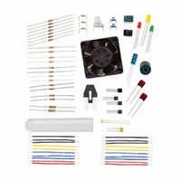
130-28176 Parallax Inc, 130-28176 Datasheet - Page 94

130-28176
Manufacturer Part Number
130-28176
Description
KIT PARTS PROCESS CONTROL
Manufacturer
Parallax Inc
Specifications of 130-28176
Accessory Type
Education Kit
Product
Microcontroller Accessories
Lead Free Status / RoHS Status
Contains lead / RoHS non-compliant
For Use With/related Products
Board of Education Full Kit
Lead Free Status / RoHS Status
Lead free / RoHS Compliant, Contains lead / RoHS non-compliant
- Current page: 94 of 330
- Download datasheet (11Mb)
Some examples of optical sensors include:
This chapter uses a close-range IR optical sensor to demonstrate operation and signal
conditioning. The sensor is used as part of sequential processes for detection and event
input.
ACTIVITY #1: CONNECTING AND TESTING THE OPTO-REFLECTIVE
SWITCH
The QRB1114 shown in Figure 4-1 is an opto-reflective switch. The actual switching
circuit is a phototransistor. Light hitting the transistor causes a current flow in the base-
emitter, which in turn causes an amplified current flow in the collector-emitter. The
package also contains an infrared LED to use as a light source (emitter). The LED emits
infrared light (IR) not visible to the human eye, and the phototransistor is most sensitive
to this wavelength of light.
In this figure, (E) is the emitter of the phototransistor, and (C) is the collector. (A) stands
for the anode of the IR LED, and (K) marks the cathode.
•
•
•
•
Using a light beam to detect presence of an object or person at a moderate
distance (several feet).
Using an emitter and detector pair for very close detection, such as motion of
your mouse, the passing of paper in a printer, or the opening of a printer cover.
Using reflected light to measure the rotation of a shaft.
Using light to transmit data at a reasonably close range (TV remote) or perhaps a
very long range (fiber-optic telecommunications).
Figure 4-1
Opto-Reflective
Switch
Related parts for 130-28176
Image
Part Number
Description
Manufacturer
Datasheet
Request
R

Part Number:
Description:
KIT PROPELLER EDU PROJECT PARTS
Manufacturer:
Parallax Inc
Datasheet:

Part Number:
Description:
KIT PARTS SMART SENSORS
Manufacturer:
Parallax Inc
Datasheet:

Part Number:
Description:
Microcontroller Modules & Accessories DISCONTINUED BY PARALLAX
Manufacturer:
Parallax Inc

Part Number:
Description:
BOOK UNDERSTANDING SIGNALS
Manufacturer:
Parallax Inc
Datasheet:

Part Number:
Description:
COMPETITION RING FOR SUMOBOT
Manufacturer:
Parallax Inc
Datasheet:

Part Number:
Description:
TEXT INFRARED REMOTE FOR BOE-BOT
Manufacturer:
Parallax Inc
Datasheet:

Part Number:
Description:
Microcontroller Modules & Accessories DISCONTINUED BY PARALLAX
Manufacturer:
Parallax Inc

Part Number:
Description:
BOOK UNDERSTANDING SIGNALS
Manufacturer:
Parallax Inc
Datasheet:

Part Number:
Description:
BOARD EXPERIMENT+LCD NX-1000
Manufacturer:
Parallax Inc
Datasheet:

Part Number:
Description:
IC MCU 2K FLASH 50MHZ SO-18
Manufacturer:
Parallax Inc
Datasheet:


