130-28176 Parallax Inc, 130-28176 Datasheet - Page 59
130-28176
Manufacturer Part Number
130-28176
Description
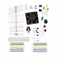
KIT PARTS PROCESS CONTROL
Manufacturer
Parallax Inc
Specifications of 130-28176
Accessory Type
Education Kit
Product
Microcontroller Accessories
Lead Free Status / RoHS Status
Contains lead / RoHS non-compliant
For Use With/related Products
Board of Education Full Kit
Lead Free Status / RoHS Status
Lead free / RoHS Compliant, Contains lead / RoHS non-compliant


PROGRAM DISCUSSION
LED
The potentiometer may simply be thought of as a variable voltage divider, such as in
Figure 3-3. Keep in mind that each of these potentiometer voltages, V(a), V(b), V(c), and
V(d), occurs as the knob on the potentiometer is turned to certain positions. Also keep in
mind that each of the voltages can be applied to P8 in Figure 3-1.
The voltage output is a function of the voltage drop to ground across the lower portion of
the potentiometer illustrated by R2 in Figure 3-3. Kirchoff's Voltage Law states that the
“algebraic sum of the voltages in a series circuit must equal the supply voltage.” The
voltage dropped across R1 and R2 must equal the supply voltage, Vdd, of 5 V. Using
Ohm's Law, the circuit may be analyzed:
The total resistance must equal the value of the potentiometer, 10 kΩ.
current flow through the resistor is:
The wiper only changes where it is tapping and splitting the total resistance. The voltage
across R
Figure 3-3 10 kΩ Voltage Divider (Do Not Build)
1
in Figure 3-1 is used to indicate the state of P8: LED On = HIGH.
Current = Voltage / Resistance or I = V/R
I = V/R = 5 V/10 kΩ = 0.5 mA
2
for Figure 3-3b can be found by:
As such, the
Related parts for 130-28176
Image
Part Number
Description
Manufacturer
Datasheet
Request
R

Part Number:
Description:
KIT PROPELLER EDU PROJECT PARTS
Manufacturer:
Parallax Inc
Datasheet:

Part Number:
Description:
KIT PARTS SMART SENSORS
Manufacturer:
Parallax Inc
Datasheet:


Part Number:
Description:
Microcontroller Modules & Accessories DISCONTINUED BY PARALLAX
Manufacturer:
Parallax Inc

Part Number:
Description:
BOOK UNDERSTANDING SIGNALS
Manufacturer:
Parallax Inc
Datasheet:


Part Number:
Description:
COMPETITION RING FOR SUMOBOT
Manufacturer:
Parallax Inc
Datasheet:


Part Number:
Description:
TEXT INFRARED REMOTE FOR BOE-BOT
Manufacturer:
Parallax Inc
Datasheet:
Part Number:
Description:
Microcontroller Modules & Accessories DISCONTINUED BY PARALLAX
Manufacturer:
Parallax Inc
Part Number:
Description:
BOOK UNDERSTANDING SIGNALS
Manufacturer:
Parallax Inc
Datasheet:
Part Number:
Description:
BOARD EXPERIMENT+LCD NX-1000
Manufacturer:
Parallax Inc
Datasheet:
Part Number:
Description:
IC MCU 2K FLASH 50MHZ SO-18
Manufacturer:
Parallax Inc
Datasheet: