HSC-ADC-EVALCZ Analog Devices Inc, HSC-ADC-EVALCZ Datasheet - Page 4
HSC-ADC-EVALCZ
Manufacturer Part Number
HSC-ADC-EVALCZ
Description
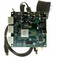
KIT EVAL ADC FIFO HI SPEED
Manufacturer
Analog Devices Inc
Datasheets
1.HSC-ADC-EVALB-DCZ.pdf
(28 pages)
2.HSC-ADC-EVALCZ.pdf
(32 pages)
3.HSC-ADC-EVALCZ.pdf
(40 pages)
Specifications of HSC-ADC-EVALCZ
Design Resources
EVALC PC Board Gerber File
Accessory Type
ADC Interface Board
Silicon Manufacturer
Analog Devices
Application Sub Type
ADC
Kit Application Type
Data Converter
Features
Buffer Memory Board For Capturing Digital Data, USB Port Interface, Windows 98, Windows 2000
Kit Contents
ADC Analyzer, Buffer Memory Board
Rohs Compliant
Yes
Lead Free Status / RoHS Status
Lead free / RoHS Compliant
For Use With/related Products
Single ADC Version
Lead Free Status / Rohs Status
Supplier Unconfirmed
Available stocks
Company
Part Number
Manufacturer
Quantity
Price
Company:

Part Number:
HSC-ADC-EVALCZ
Manufacturer:
Analog Devices Inc
Quantity:
135


AN-905
QUICK START FOR ADC EVALUATION
With VisualAnalog, it is easy to bypass the canvas interface and
begin ADC evaluation immediately. To begin interfacing to a
particular ADC right away, use the following steps:
1. Connect and power the evaluation board, ADC data capture
2. Connect the ADC data capture board to the computer
3.
4.
board, and any other required board used for data transfer.
You can also supply the required clock and input signals to
the ADC evaluation board.
with a high speed USB cable. If a driver installation dialog
appears, as happens when using the ADC data capture
board for the first time, proceed through the dialog steps.
If the Hardware Wizard appears (see Figure 2), follow the
instructions to install the software automatically. This allows
Windows to complete the driver installation process.
Start VisualAnalog. For more information, see the
VISUALANALOG Software section.
The start-up form now appears. If an ADC was connected
using the preceding steps, VisualAnalog attempts to detect
it and selects the canvas template that supports the ADC
on the start-up form. Note that the ADC must support
SPI® functionality for the program to autodetect. If the
ADC does not support SPI, or if the program does not
detect the ADC for any reason, manually select the tem-
plate. See the Using the Start-Up Form section for more
information.
Figure 2. Hardware Wizard
Rev. 0 | Page 4 of 40
5.
6.
A Graph form should appear with the FFT results. If the graph
does not appear, it is possible there was an error during
processing. Check the board connection and try again. If this
does not fix the problem, expand the main form and check the
canvas settings. For more information, see the Using the Main
Form and the Components Overview sections.
7. The main form appears in collapsed mode with your canvas
Select the FFT icon and click Open.
If you have an HSC-ADC-EVALC data capture board, a
dialog box that asks for permission to configure the on
board FPGA may appear. If you prefer to use the current
FPGA configuration, click No to bypass configuration.
Otherwise, click Yes to configure the FPGA. See the Using
the Start-Up Form section for more information.
open and selected. Click Update to run the canvas.
Figure 4. FPGA Configuration Dialog
Figure 3. New Canvas Form
Figure 5. Update Button
Related parts for HSC-ADC-EVALCZ
Image
Part Number
Description
Manufacturer
Datasheet
Request
R

Part Number:
Description:
KIT EVAL ADC FIFO DUAL-CH USB HS
Manufacturer:
Analog Devices Inc
Datasheet:

Part Number:
Description:
KIT EVAL ADC USB FIFO HI-SPEED
Manufacturer:
Analog Devices Inc
Datasheet:

Part Number:
Description:
BOARD FPGA OCTAL LVDS FOR ADC
Manufacturer:
Analog Devices Inc
Datasheet:
Part Number:
Description:
KIT EVAL FOR SINGLE CHAN HSC ADC
Manufacturer:
Analog Devices Inc

Part Number:
Description:
KIT EVAL FOR DUAL ADC/CONV
Manufacturer:
Analog Devices Inc
Datasheet:
Part Number:
Description:
KIT EVAL ADC USB FIFO HI-SPEED
Manufacturer:
Analog Devices Inc
Datasheet:

Part Number:
Description:
KIT EVAL ADC USB FIFO HI-SPEED
Manufacturer:
Analog Devices Inc
Datasheet:
Part Number:
Description:
KIT EVAL ADC FIFO DUAL-CH USB HS
Manufacturer:
Analog Devices Inc
Datasheet:
Part Number:
Description:
BOARD FPGA QUAD LVDS FOR ADC
Manufacturer:
Analog Devices Inc
Datasheet:
Part Number:
Description:
Adapter For AD922x Family
Manufacturer:
Analog Devices Inc
Datasheet:
Part Number:
Description:
Interposer Quad/octal ADCs
Manufacturer:
Analog Devices Inc
Datasheet:

Part Number:
Description:
±1.7g Dual-Axis IMEMS Accelerometer Evaluation Board
Manufacturer:
Analog Devices Inc
Datasheet:

Part Number:
Description:
IC MULTIPLIER ANALOG 8-SOIC T/R
Manufacturer:
Analog Devices Inc
Datasheet:
Part Number:
Description:
IC ANALOG MULTIPLIER 8-DIP
Manufacturer:
Analog Devices Inc
Datasheet: