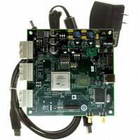
HSC-ADC-EVALCZ Analog Devices Inc, HSC-ADC-EVALCZ Datasheet - Page 22

HSC-ADC-EVALCZ
Manufacturer Part Number
HSC-ADC-EVALCZ
Description
KIT EVAL ADC FIFO HI SPEED
Manufacturer
Analog Devices Inc
Datasheets
1.HSC-ADC-EVALB-DCZ.pdf
(28 pages)
2.HSC-ADC-EVALCZ.pdf
(32 pages)
3.HSC-ADC-EVALCZ.pdf
(40 pages)
Specifications of HSC-ADC-EVALCZ
Design Resources
EVALC PC Board Gerber File
Accessory Type
ADC Interface Board
Silicon Manufacturer
Analog Devices
Application Sub Type
ADC
Kit Application Type
Data Converter
Features
Buffer Memory Board For Capturing Digital Data, USB Port Interface, Windows 98, Windows 2000
Kit Contents
ADC Analyzer, Buffer Memory Board
Rohs Compliant
Yes
Lead Free Status / RoHS Status
Lead free / RoHS Compliant
For Use With/related Products
Single ADC Version
Lead Free Status / Rohs Status
Supplier Unconfirmed
Available stocks
Company
Part Number
Manufacturer
Quantity
Price
Company:
Part Number:
HSC-ADC-EVALCZ
Manufacturer:
Analog Devices Inc
Quantity:
135
AN-905
You can use the ADC data capture board to capture data from
the high speed ADCs. Interfacing with the data capture board is
via USB.
FIFO configuration allows the sample rate and sample size to
be set. Although sample rate is relative, sample size may be no
larger than the physical memory available on the FIFOs.
Normally, the HSC-ADC-EVALA and HSC-ADC-EVALB
boards have 32-KB devices. It is possible to reconfigure them
with compatible 256-KB devices. The HSC-ADC-EVALC board
can support various sample sizes, depending on the current
FPGA configuration.
Figure 47. FIFO4.x Interface
Rev. 0 | Page 22 of 40
In addition, you can select the channels to enable which devices
are present. The interface supports both dual- and single-
channel devices. Access the output from the ADC data at the
output nodes on the right side of the component. The A and B
channels are output separately, with the A data on the top node
and B data on the bottom node.
An Input Formatter must always follow the ADC Data
Capture component if you want to perform processing within
the canvas. The only exception to this rule is Logic Analysis.
The Input Formatter takes the resolution and alignment of the
ADC into account when moving data into the environment of
VisualAnalog. For more information on setting up the Input
Formatter, see the Input Formatter section.
Most of the Analog Devices ADC evaluation boards are MSB-
justified to 16 bits and, therefore, the Alignment check box
within the Input Formatter should be set to 16 bits. The reso
lution on the Input Formatter should be set to the native
resolution of the ADC. Number Format should be set in
accordance with the data format of the ADC.


